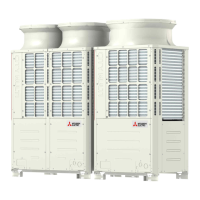
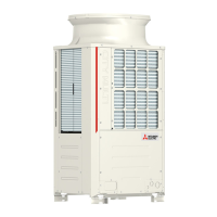
What to do if my Mitsubishi Electric Air Conditioner has a water supply cutoff?
- PpaulweaverSep 9, 2025
If your Mitsubishi Electric Air Conditioner experiences a water supply cutoff, ensure the water supply is connected and operational.

What to do if my Mitsubishi Electric Air Conditioner has a water supply cutoff?
If your Mitsubishi Electric Air Conditioner experiences a water supply cutoff, ensure the water supply is connected and operational.
What to do if my Mitsubishi Electric Air Conditioner has a high pressure fault?
If your Mitsubishi Electric Air Conditioner shows a high pressure fault, check for any obstructions in the refrigerant system.
What to do if my Mitsubishi Electric PUHY-RP200 has a low pressure fault?
If your Mitsubishi Electric Air Conditioner is showing a low pressure fault, verify the refrigerant levels.
What to do if there is a refrigerant overcharge in my Mitsubishi Electric PUHY-RP200?
If your Mitsubishi Electric Air Conditioner has a refrigerant overcharge, adjust the refrigerant levels.
How to fix heatsink overheat protection on my Mitsubishi Electric Air Conditioner?
If your Mitsubishi Electric Air Conditioner is experiencing heatsink overheat protection, ensure proper ventilation and cooling.
What causes a drain pump fault in Mitsubishi Electric Air Conditioner?
If you suspect a drain pump fault in your Mitsubishi Electric Air Conditioner, inspect the drain pump for any damage or blockages.
What to do if my Mitsubishi Electric Air Conditioner shows ACCT sensor fault?
If your Mitsubishi Electric Air Conditioner shows an ACCT sensor fault, inspect the ACCT sensor.
How to resolve address setting error on Mitsubishi Electric PUHY-RP200 Air Conditioner?
If you encounter an address setting error on your Mitsubishi Electric Air Conditioner, ensure proper addressing of all units.
What to do if my Mitsubishi Electric PUHY-RP200 Air Conditioner shows temperature sensor fault TH5?
If your Mitsubishi Electric Air Conditioner displays a temperature sensor fault at the accumulator inlet temperature (TH5), ensure proper function of the temperature sensor.
What to do if my Mitsubishi Electric Air Conditioner has temperature sensor fault (TH24)?
If your Mitsubishi Electric Air Conditioner is showing a temperature sensor fault for the outside temperature (TH24), check the sensor for proper connections.
| Model | PUHY-RP200 |
|---|---|
| Category | Air Conditioner |
| Type | Heat Pump |
| Refrigerant | R410A |
| Power Supply | 380-415V, 50Hz |
Essential checks and information before performing any service work on the unit.
List of required tools and materials for installation and servicing of the unit.
Guidelines for storing refrigerant piping materials to prevent contamination.
Instructions on preparing refrigerant piping, including lubrication of flares and flanges.
Procedures and precautions for brazing refrigerant pipes to ensure system integrity.
Method for performing an air tightness test on the refrigerant system using nitrogen.
Procedures and standards for vacuum drying the refrigerant circuit to remove moisture.
Guidelines and precautions for charging refrigerant into the system in liquid phase.
Steps to take and methods for replenishing refrigerant in case of a leak.
Comparison of chemical and pressure characteristics between R22 and R410A refrigerants.
Information on refrigerating machine oil for HFC systems and effects of contaminants.
Summary of compatible indoor units with different outdoor units and standard combinations.
Guidelines for control wiring, including cable types and maximum allowable lengths.
Instructions for setting switches and addresses for various units and controllers.
Examples of typical system connections for MA and ME remote controllers.
Detailed wiring and cautions for a system with an MA remote controller.
Detailed wiring and cautions for a system with an ME remote controller.
Wiring examples and cautions for systems with both MA and ME remote controllers.
Criteria for determining reusability of existing piping and restrictions on pipe length.
Diagrams and descriptions of outdoor unit components and the refrigerant circuit.
Overview of the control box, its internal components, and high-voltage warnings.
Detailed layout and description of the outdoor unit control board and its connectors.
Comparison of functions, specifications, and selection criteria for MA and ME remote controllers.
Procedures for performing group operations and interlock settings using the ME remote controller.
Procedure for setting interlocks between LOSSNAY units and indoor units using the MA remote controller.
Instructions on how to select the temperature detection position using the remote controller's sensor.
Detailed electrical wiring diagram for the outdoor unit, including component explanations.
Electrical wiring diagram for the transmission booster unit, showing connections and components.
Schematic diagram of the refrigerant circuit for various outdoor unit models.
Description of principal parts of the refrigerant circuit and their functions and specifications.
Detailed explanation of dipswitch functions and factory settings for outdoor unit control.
Overview of control methods, startup sequences, and operating modes for outdoor units.
Flowcharts illustrating operation modes for indoor and outdoor units, including cooling, heating, and dry.
Pre-test run checks including refrigerant leaks, wiring, and power supply.
Step-by-step procedure for performing a test run using the MA remote controller.
Understanding refrigerant characteristics and operating conditions for system adjustment.
Guidance on identifying and correcting refrigerant overcharging or undercharging issues.
Procedures for using the automatic refrigerant charge adjustment mode.
Description of normal operating symptoms that may appear during test runs.
Reference data for standard operating conditions during cooling and heating.
Comprehensive list of error codes, their definitions, and searched units.
Guidance on interpreting and responding to error codes displayed on the remote controller.
Methods for investigating transmission line issues, including wave shape and noise analysis.
Detailed troubleshooting steps for key components like sensors, valves, and boards.
Procedures for locating and repairing refrigerant leaks in both indoor and outdoor units.
Step-by-step instructions for safely removing and replacing the compressor.
Guide to interpreting outdoor unit LED error displays for troubleshooting.
Explanation of how to interpret LED displays on the service monitor for unit status.


