EasyManua.ls Logo

Mitsubishi Electric PUMY-HP42NKMU2 User Manual

Mitsubishi Electric PUMY-HP42NKMU2
190 pages
To Next Page IconTo Next Page
Page #1 background imageLoading...
Page #1 background image
TECHNICAL & SERVICE MANUAL
OUTDOOR UNIT
No. OCH811
REVISED EDITION-A
HFC
utilized
R410A
September 2023
Note:
Specifications have been
changed in REVISED
EDITION-A.
<Outdoor unit>
[Model Name]
Model name
indication
PARTS CATALOG (OCB811)
PUMY-P36NKMU4
PUMY-P48NKMU4
PUMY-P60NKMU4
PUMY-HP36NKMU2
PUMY-HP42NKMU2
PUMY-HP48NKMU2
PUMY-P36NKMU4
PUMY-P48NKMU4
PUMY-P60NKMU4
PUMY-HP36NKMU2
PUMY-HP42NKMU2
PUMY-HP48NKMU2
[Service Ref.]
SPLIT-TYPE, HEAT PUMP AIR CONDITIONERS
CONTENTS
1. SAFETY PRECAUTION ·······················2
2. OVERVIEW OF UNITS ························5
3. SPECIFICATIONS ···························· 11
4. DATA ·············································· 14
5. OUTLINES AND DIMENSIONS ··········· 36
6. WIRING DIAGRAM ··························· 37
7. NECESSARY CONDITIONS
FOR SYSTEM CONSTRUCTION ········· 40
8. TROUBLESHOOTING ······················· 55
9. ELECTRICAL WIRING ·····················133
10. REFRIGERANT PIPING TASKS ·········139
11. DISASSEMBLY PROCEDURE ···········147
12. REMOTE CONTROLLER ··················168
OCH811 is void.
Question and Answer IconNeed help?

Do you have a question about the Mitsubishi Electric PUMY-HP42NKMU2 and is the answer not in the manual?

Mitsubishi Electric PUMY-HP42NKMU2 Specifications

General IconGeneral
RefrigerantR410A
Cooling Capacity (BTU)42000 BTU/hr
Heating Capacity (BTU)48000 BTU/hr
SEER16.0
Voltage208-230V
PhaseSingle

Summary

Safety Precautions for Refrigerant Handling

Preparation and Precautions for Repair Service

Essential steps before repair, including tool preparation, ventilation, and power disconnection.

Capacity Selection and Correction

Wiring Diagram and Switch Settings

Model Selection Switch Settings

Explanation of DIP switch settings (SW1-SW9) for model selection, function configuration, and unit address.

System Construction and Control Wiring

Refrigerant System Diagram

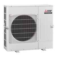
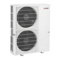
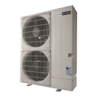
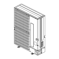
Schematic diagrams illustrating the refrigerant flow and component layout for various outdoor unit models.

Troubleshooting Common Errors

Checkpoints for Test Run Procedures

Pre-test run checks, safety inspections, and operational procedures for ensuring proper system startup.

Countermeasures for Test Run Errors

Table of check codes, troubles, detected units, and recommended countermeasures for test run abnormalities.

Self-Diagnosis Action Flowcharts

Diagnostic flowcharts for common errors like serial communication failure and compressor issues.

Troubleshooting Specific Check Codes

Detailed troubleshooting steps for various error codes related to compressor, sensors, and power supply.

Remote Controller Functions and Operation

Error Information and Reset Procedures

Steps to check and reset error codes displayed on the remote controller, including navigating through screens.

Self-Diagnosis Methods for Remote Controller

Procedure for performing self-diagnosis on the remote controller to identify malfunctions and reset errors.

Remote Controller Malfunction Diagnosis

Methods for diagnosing malfunctions on PAR-FL32MA and PAR-SL101A-E remote controllers.

Remote Controller Check Procedure

Steps to diagnose remote controller issues, including checking display, transmission line, and controller health.

Electrical Wiring Guidelines

Refrigerant Piping Tasks and Calculations

Refrigerant Piping System Configuration

Diagrams and tables showing piping diameters for different connection methods and unit models.

Additional Refrigerant Charge Calculation

Methodology for calculating and charging additional refrigerant based on liquid pipe size, length, and capacity.

Precautions Against Refrigerant Leakage

Guidelines to prevent refrigerant leakage and maintain safe concentration levels in rooms.

Disassembly Procedures

Component Check Procedures

Checking Thermistors and Fan Motors

Methods for checking thermistor resistance and fan motor continuity, including voltage checks.

Checking Solenoid Valves, Compressor, and LEV

Procedures for checking solenoid valves, compressor resistance, and linear expansion valves.

Checking Power Circuit and Control Boards

Methods for checking power circuit boards, multi-controller circuit boards, and M-NET power circuit boards.

Checking Outdoor Noise Filter and M-NET Boards

Detailed checks for outdoor noise filter circuit boards and M-NET power circuit boards.

Related product manuals