What to do if my Mitsubishi Electric PURY-P250 Air Conditioner has a drain pump abnormality?
- JJennifer SmithAug 28, 2025
If your Mitsubishi Electric Air Conditioner is showing a drain pump abnormality, check Code List 2502.

What to do if my Mitsubishi Electric PURY-P250 Air Conditioner has a drain pump abnormality?
If your Mitsubishi Electric Air Conditioner is showing a drain pump abnormality, check Code List 2502.
What to do if my Mitsubishi Electric Air Conditioner displays a thermal sensor abnormality?
If your Mitsubishi Electric Air Conditioner shows a thermal sensor abnormality, check Code List 5101.
What to do if my Mitsubishi Electric Air Conditioner shows fan speed abnormality (motor abnormality) (IC, LC)?
If you're encountering a fan speed abnormality (motor abnormality) (IC, LC) with your Mitsubishi Electric Air Conditioner, check Code List 4116.
What to do if my Mitsubishi Electric Air Conditioner is leaking water (LC)?
If you are experiencing water leakage (LC) with your Mitsubishi Electric Air Conditioner, check Code List 2600.
What to do if my Mitsubishi Electric PURY-P250 has a water leakage abnormality?
If you notice a water leakage abnormality with your Mitsubishi Electric Air Conditioner, check Code List 2500.
| Series | PURY |
|---|---|
| Refrigerant | R410A |
| Power Supply | 380-415V, 50Hz |
| Indoor Unit Dimensions (W x H x D) | Varies by model |
| Weight (Indoor Unit) | Varies by model |
Covers general safety, warning/caution symbols, manual handling, and installation precautions.
Details installation safety, unit placement, electrical work, and operational safety precautions.
Precautions for refrigerant leaks, handling, and system safety features.
Proper grounding, power supply wiring, breakers, and water spray precautions.
Steps before test run, including power on duration, wet hands, pipe contact, and panel usage.
Reading before servicing, tools, materials, and piping preparation.
Brazing, air tightness test, vacuum drying, refrigerant charging, and leak remedies.
Comparison of refrigerants and notes on machine oil.
Compatible units, cable types, lengths, and switch/address settings.
Examples of system connections for MA, M-NET, and combined controllers.
Guidelines for allowable pipe lengths based on system configuration.
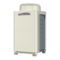
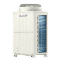
Front view of outdoor unit and its main components.
Diagrams illustrating refrigerant flow for various outdoor unit models.
Components within the BC controller's control box.
Layout and components of the outdoor unit control board.
Comparing functions, specifications, wiring, and connection methods of MA and M-NET controllers.
Criteria for choosing between MA and M-NET remote controllers based on system needs.
Procedures for group and interlock settings using ME remote controller.
Procedures for setting LOSSNAY interlocks with the MA remote controller.
Detailed electrical wiring diagram for the outdoor unit.
Electrical wiring diagram for the BC controller.
Diagrams illustrating refrigerant flow for various outdoor unit models.
Explanation of key components in the refrigerant circuit.
Functions and factory settings of dipswitches on outdoor unit control board.
Outline of control methods, startup sequences, and initial control.
Control details for solenoid valves, LEV, and SVMs in BC controllers.
Flowcharts for indoor and outdoor unit operation modes.
Essential checks before initiating a test run.
Step-by-step guide for performing a test run.
Understanding characteristics and adjusting refrigerant levels.
Reference data for standard operating conditions.
Comprehensive list of error codes, preliminary codes, and definitions.
Procedures for handling errors shown on the remote controller.
Troubleshooting steps for various faults including temperature and pressure sensors.
Steps for identifying and fixing refrigerant leaks.
Instructions for replacing the compressor.
Diagnostic flow for LEV solenoid valves.
Guide to reading LED displays, including numerical and flag formats.
Functionality of the outdoor unit's clock for time and error data storage.
Current data displayed on the LED monitor for various items.


