Do you have a question about the Mitsubishi Electric PUZ-A18NHA4 and is the answer not in the manual?
| Cooling Capacity (kW) | 5.0 |
|---|---|
| Refrigerant | R410A |
| Phase | 1 |
| Outdoor Unit Noise Level | 50 |
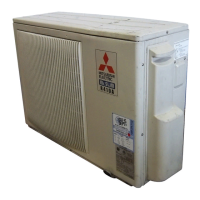
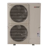
| Series | PUZ |
| Heating Capacity (kW) | 5.6 kW |
| Voltage (V) | 208/230 |
| Hertz (Hz) | 50 |
| Coefficient of Performance (Heating) | 4.0 |
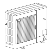
| Outdoor Unit Dimensions (HxWxD) | 540 x 800 x 290 |
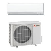
| Indoor Unit Dimensions (HxWxD) | 290 x 900 x 210 |
Lists indoor unit models, service references, and manual numbers.
General safety instructions before accessing electrical terminals.
Specific safety precautions for R410A refrigerant.
Specifies pipe thickness and flare dimensions for R410A due to higher working pressure and air tightness.
Table showing compatibility of R410A tools with R22 tools.
Pre-charged refrigerant system for specific piping lengths.
Table detailing refrigerant charge amounts based on piping length.
Technical specifications for compressors, including winding resistance.
Noise level curves for different unit models in cooling and heating modes.
Standard operation data for various models.
Standard operation data for heat pump models in cooling and heating.
Standard operation data for cooling-only models.
Specifies minimum clearances required around the outdoor unit for installation.
Instructions for securing the unit with foundation bolts.
Indicates that piping and wiring connections are made from the rear direction only.
Details the locations and types of knockout holes for piping and wiring.
Explains the model selection using DIP switches SW6 and SW5.
Lists components and their functions related to the M-NET adapter.
Details wiring specifications for systems where the outdoor unit supplies power to the indoor unit.
How to set the M-NET address for outdoor units.
How to set refrigerant addresses for indoor units in multi-group systems.
Rules for setting addresses in multiple grouping systems.
Procedure for recovering refrigerant when moving units.
Steps to start and finish a test run of the unit.
Procedure for performing a test run using a wireless remote controller.
Summary of actions based on error code display and trouble recurrence.
Pre-run checks before starting a test run.
Methods for accessing and using self-diagnosis functions.
Detailed table of abnormalities, cases, and corrective actions.
Diagnosing common operational issues and user complaints.
Resistance values and check procedures for various thermistors.
Checking procedures for motors, solenoid coils, and expansion valves.
Thermistor resistance charts and formulas for low temperature applications.
Thermistor resistance charts and formulas for medium temperature applications.
Thermistor resistance charts and formulas for high temperature applications.
Summary of operation and pulse signal interpretation for LEV.
Details on linear expansion valve operation based on pulse signals.
Summary of operation and pulse signal interpretation for LEV.
Details on linear expansion valve operation based on pulse signals.
Items to check, cautions, and steps to activate emergency operation.
Procedure to deactivate emergency operation.
Data items displayed and their values during emergency operation.
Diagram showing test points on the outdoor controller circuit board.
Diagram of the outdoor noise filter circuit board with component labels.
Diagram of the outdoor power circuit board with test points and connections.
Diagram and test points for the active filter module.
Details the functions and settings of various DIP and push switches.
Details the function of the CN31 connector for emergency operation.
How to enable low-level sound priority mode via external signal.
How to enable demand control via external input for power consumption reduction.
Normal LED indicators for the outdoor controller board and A-Control Service Tool.
Abnormal LED blinking patterns and corresponding error codes/inspection methods.
How to access and operate maintenance mode.
How to fix operating frequency for stable inspection.
How to select data items for display in maintenance mode.
How to set unit functions using the wired remote controller.
Details on function settings for different unit numbers and system types.
Step-by-step guide for selecting functions via wired remote controller.
Guide for selecting functions using a wireless remote controller.
Detailed procedures for changing language, limits, modes, and displays.
How to select the display language.
How to set operation limits, automatic mode, and controller roles.
How to set temperature limits for cooling, heating, and auto modes.
How to change temperature unit and room air temperature display settings.
Procedure for setting temperature display units (°C/°F) using the wireless remote.
Steps to enter maintenance monitor mode and request data.
How to use the service inspection monitor to view data.
How to exit monitoring mode and return to normal operation.
Detailed explanations for various request codes related to operation and control states.
Details of fan control states and actuator output states.
Details of error contents (U9) based on request code 55.
Details on contact demand capacity and external input states.
Details on outdoor unit capacity and setting information.
Tables detailing outdoor unit switch settings and corresponding data displays.
Details on indoor unit model, capacity, and wireless pair settings.
Steps to remove external panels of the outdoor unit.
Steps to remove the fan motor assembly.
Steps to remove the electrical parts box.
Steps to remove outdoor thermistors for pipe, phase, shell, and discharge.
Steps to remove 4-way valve, LEV, bypass valve coils, and switches.
Steps to remove the compressor and accumulator.
Steps to remove the reactor and capacitor.