SERVICE MANUAL
No.OCH774
REVISED EDITION-A
SPLIT-TYPE AIR CONDITIONERS
R32
January 2023
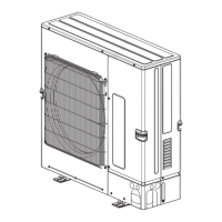
Outdoor unit
[Model Name]
PUZ-SM100VKA2
PUZ-SM125VKA2
PUZ-SM140VKA2
PUZ-SM100YKA2
PUZ-SM125YKA2
PUZ-SM140YKA2
[Service Ref.]
PUZ-SM100VKA2.TH
PUZ-SM125VKA2.TH
PUZ-SM140VKA2.TH
PUZ-SM100YKA2.TH
PUZ-SM125YKA2.TH
PUZ-SM140YKA2.TH
PARTS CATALOG (OCB774)
CONTENTS
1. REFERENCE MANUAL ·························· 2
2. SAFETY PRECAUTION ·························· 2
3. SPECIFICATIONS ································12
4. DATA ·················································· 13
5. OUTLINES AND DIMENSIONS ···············16
6. WIRING DIAGRAM ·······························17
7. WIRING SPECIFICATIONS ····················20
8. REFRIGERANT SYSTEM DIAGRAM ·······25
9. TROUBLESHOOTING ···························27
10. FUNCTION SETTING ····························74
11. MONITORING THE OPERATION
DATA BY THE REMOTE CONTROLLER ··75
12. EASY MAINTENANCE FUNCTION ··········83
13. DISASSEMBLY PROCEDURE ···············85
14. REMOTE CONTROLLER ·······················91
Revision:
• Connectable indoor units
have been added in
REVISED EDITION-A.
OCH774 is void.