EasyManua.ls Logo

Mitsubishi Electric TRANE CITY MULTI TPKFYP004LM140A User Manual

Mitsubishi Electric TRANE CITY MULTI TPKFYP004LM140A
38 pages
To Next Page IconTo Next Page
Page #1 background imageLoading...
Page #1 background image
TECHNICAL & SERVICE MANUAL
Indoor unit
[Model Name] [Service Ref.]
INDOOR UNIT
R410A
Model name
indication
PARTS CATALOG (OCBT715)
No. OCHT715
REVISED EDITION-A
June 2021
Note:
• This manual describes
service data of the indoor
units only.
TPKFYP004LM140A
TPKFYP004LM140A
TPKFYP006LM140A
TPKFYP006LM140A
TPKFYP008LM140A
TPKFYP008LM140A
TPKFYP012LM140A
TPKFYP012LM140A
TPKFYP015LM140A
TPKFYP015LM140A
TPKFYP018LM140A
TPKFYP018LM140A
Revision:
Outlines and dimensions
have been modified
in REVISED EDITION-A.
Revision:
Outlines and dimensions
have been modified
in REVISED EDITION-A.
Revision:
Outlines and dimensions
have been modified
in REVISED EDITION-A.
OCHT715 is void.
CONTENTS
1. SAFETY PRECAUTION ·······················2
2. PARTS NAMES AND FUNCTIONS ········4
3. SPECIFICATION ······························ 12
4. NOISE CRITERION CURVES ············· 15
5. OUTLINES AND DIMENSIONS ··········· 17
6. WIRING DIAGRAM ··························· 19
7. REFRIGERANT SYSTEM DIAGRAM ··· 20
8. MICROPROCESSOR CONTROL ········· 20
9. TROUBLESHOOTING ······················· 27
10. DISASSEMBLY PROCEDURE ············ 35
Question and Answer IconNeed help?

Do you have a question about the Mitsubishi Electric TRANE CITY MULTI TPKFYP004LM140A and is the answer not in the manual?

Mitsubishi Electric TRANE CITY MULTI TPKFYP004LM140A Specifications

General IconGeneral
CategoryAir Conditioner
ModelTPKFYP004LM140A
BrandMitsubishi Electric TRANE
Product LineCITY MULTI
RefrigerantR410A
Airflow (High Speed)850 m³/h
Power Supply220-240V, 50Hz

Summary

Safety Precautions

Parts Names and Functions

Indoor Unit Components

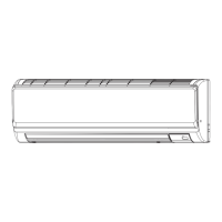
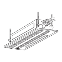
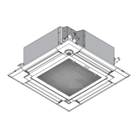
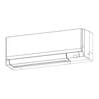
Identifies and describes components of the indoor unit, including filters and louvers.

Wired Remote Controller Functions

Details the functions and capabilities of the wired remote controller.

Specifications

Unit Specifications

Lists technical specifications such as cooling/heating capacity, power, and dimensions.

Electrical Parts Specifications

Details electrical components, including thermistors, motors, and terminal blocks.

Noise Criterion Curves

Outlines and Dimensions

Wiring Diagram

Refrigerant System Diagram

Microprocessor Control

Cool Operation Control

Explains how to operate the unit in cooling mode using the remote controller.

Dry Operation Control

Details the operation and control functions for dry mode.

Fan Operation Control

Outlines the control logic and settings for fan-only operation.

Heat Operation Control

Describes the procedures and settings for heating mode operation.

Auto Operation Control

Explains the automatic switching between cooling and heating modes.

Stopped Unit Control Mode

Details control functions when the unit is in a stopped state.

Troubleshooting

Part Checking Procedures

Provides methods for testing individual components like thermistors and motors.

DIP Switch Functions

Explains the purpose and settings of various DIP switches for function configuration.

Test Point Diagrams

Illustrates key test points on the indoor controller board for diagnostics.

Disassembly Procedure

Removing the Panel

Step-by-step guide for safely removing the unit's front panel and covers.

Removing the Electrical Box

Instructions for accessing and removing the main electrical enclosure.

Removing Electronic Boards

Steps for removing electronic boards, including controller and address boards.

Removing Nozzle Assembly and Drain Hose

Procedure for removing the air outlet nozzle assembly and drain hose.

Removing Vane Motor

Details on how to remove the vane motors from the unit.

Removing Fan Motor and Fan

Guide for disassembling and removing the indoor fan motor and fan.

Removing Pipe Thermistors

Instructions for removing pipe temperature sensors.

Removing Heat Exchanger and LEV

Procedure for removing the heat exchanger and linear expansion valve.

Removing Room Temperature Thermistor

Steps for removing the room temperature sensor.

Related product manuals