EasyManua.ls Logo

Mitsubishi Electric TRANE TPLFYP012FM140A User Manual

Mitsubishi Electric TRANE TPLFYP012FM140A
40 pages
To Next Page IconTo Next Page
Page #1 background imageLoading...
Page #1 background image
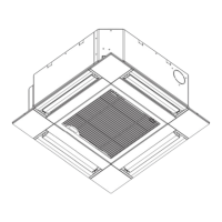
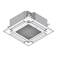
Indoor unit
[Model Name]
TPLFYP005FM140A
TPLFYP008FM140A
TPLFYP012FM140A
TPLFYP015FM140A
TPLFYP018FM140A
R410A
TECHNICAL & SERVICE MANUAL
April 2019
No. TCHT003
INDOOR UNIT


CONTENTS
1. SAFETY PRECAUTION
..........................
2
2. PARTS NAMES AND FUNCTIONS
........
4
3. SPECIFICATIONS
.................................
13
4. 4-WAY AIR FLOW SYSTEM
.................
15
5. OUTLINES AND DIMENSIONS
............
17
6. WIRING DIAGRAM
...............................
18
7.
REFRIGERANT SYSTEM DIAGRAM
......
19
8. MICROPROCESSOR CONTROL
..........
20
9. TROUBLESHOOTING
..........................
27
10. DISASSEMBLY PROCEDURE
........... 35
PARTS CATALOG (TCBT003)
Question and Answer IconNeed help?

Do you have a question about the Mitsubishi Electric TRANE TPLFYP012FM140A and is the answer not in the manual?

Mitsubishi Electric TRANE TPLFYP012FM140A Specifications

General IconGeneral
CategoryAir Conditioner
Cooling Capacity12000 BTU/h
Heating Seasonal Performance Factor (HSPF)10.0
Power Supply208-230V, 1 Phase, 60Hz
RefrigerantR410A
Operating Temperature (Cooling)14 to 115 °F (-10 to 46 °C)
Operating Temperature (Heating)75 °F

Summary

Safety Precautions

Cautions for New Refrigerant Handling

Key safety measures and warnings related to R410A refrigerant.

Service Procedures and Tools

Guidelines for service operations and essential tools for R410A systems.

Parts and Functions Overview

Wired Remote Controller <TAR-40MAA> Details

Interface and Button Operations

Overview of the controller's display, buttons, and operating modes.

Detailed Button Functions

Explanation of individual button functions like ON/OFF, MENU, and Function buttons.

Main Menu Configuration Options

System Settings and Configuration

Wireless Remote Controller <TAC-YT53CRAU>

Wireless Remote Controller Operation

Technical Specifications

General Unit Specifications

Lists key performance data like cooling/heating capacity, dimensions, and weight.

Wiring Diagrams

Indoor Unit Electrical Connections

Schematics illustrating the wiring of indoor controller board and components.

Refrigerant System Diagram

Refrigerant Circuit Layout

Diagram showing the flow of refrigerant and key components like expansion valve.

Microprocessor Control

Cool Operation Control

Details on controlling temperature, fan speed, and anti-freeze in cooling mode.

Microprocessor Control - Operation Modes

Dry Operation Control

Control logic for dry operation, including fan and drain pump.

Heat Operation Control

Temperature and Fan Settings

Control logic for temperature adjustment and fan speed during heating.

Heat Operation Specific Modes

Automatic and Stopped Operation

Auto Operation Logic

Control logic for automatic switching between cool and heat modes.

Troubleshooting - Error Codes

Test Run Error Countermeasures

Lists error codes, their causes, and recommended troubleshooting steps.

Part Inspection and Troubleshooting

Thermistor and Motor Checks

Procedures for checking thermistors, vane motors, and drain pump components.

Sensor and Valve Checks

Instructions for testing float switches, i-see sensors, and linear expansion valves.

Linear Expansion Valve Troubleshooting

Fan Motor and Controller Checks

Fan Motor and Wiring Inspection

Procedures for inspecting the fan motor, its wiring, and the controller board.

Power Supply Verification

Steps to check power supply voltages to the fan motor and controller.

DIP Switch Functions

Indoor Controller Board Test Points

Component Identification and Test Points

Diagram of the indoor controller board with labeled components and test points.

Disassembly Procedure - Initial Steps

Disassembly Procedure - Component Removal

Disassembly Procedure - Motor and Heat Exchanger

Disassembly Procedure - Pump and Heat Exchanger

Related product manuals