EasyManua.ls Logo

Mitsubishi Electric TRANE TPLFYP018FM140A User Manual

Mitsubishi Electric TRANE TPLFYP018FM140A
40 pages
To Next Page IconTo Next Page
Page #1 background imageLoading...
Page #1 background image
Indoor unit
[Model Name]
TPLFYP005FM140A
TPLFYP008FM140A
TPLFYP012FM140A
TPLFYP015FM140A
TPLFYP018FM140A
R410A
TECHNICAL & SERVICE MANUAL
April 2019
No. TCHT003
INDOOR UNIT


CONTENTS
1. SAFETY PRECAUTION
..........................
2
2. PARTS NAMES AND FUNCTIONS
........
4
3. SPECIFICATIONS
.................................
13
4. 4-WAY AIR FLOW SYSTEM
.................
15
5. OUTLINES AND DIMENSIONS
............
17
6. WIRING DIAGRAM
...............................
18
7.
REFRIGERANT SYSTEM DIAGRAM
......
19
8. MICROPROCESSOR CONTROL
..........
20
9. TROUBLESHOOTING
..........................
27
10. DISASSEMBLY PROCEDURE
........... 35
PARTS CATALOG (TCBT003)
Question and Answer IconNeed help?

Do you have a question about the Mitsubishi Electric TRANE TPLFYP018FM140A and is the answer not in the manual?

Mitsubishi Electric TRANE TPLFYP018FM140A Specifications

General IconGeneral
BrandMitsubishi Electric
ModelTRANE TPLFYP018FM140A
CategoryAir Conditioner
LanguageEnglish

Summary

SAFETY PRECAUTION

New Refrigerant Cautions

General safety precautions for using new refrigerant.

Service Cautions

Important warnings and procedures for servicing the unit.

Refrigerant Charge Guidelines

Guidelines for charging refrigerant into the system.

PARTS NAMES AND FUNCTIONS

TAR-40MAA Controller Interface

Detailed explanation of the TAR-40MAA wired remote controller interface and buttons.

Remote Controller Menu Navigation

Main Menu Setting Details

Detailed list of settings available in the main menu for various functions.

TAC-YT53CRAU Controller

Explanation of the TAC-YT53CRAU wired remote controller and its display icons.

Wireless Remote Controller

Overview of the wireless remote controller, buttons, and display functions.

Technical Specifications

Product Specifications

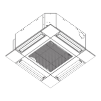
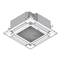
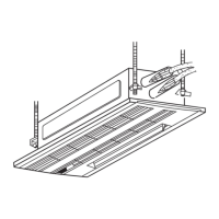
Technical specifications for various indoor unit models including dimensions, capacity, and noise levels.

Electrical Component Specs

Electrical specifications of components like thermistors, motors, fuses, and terminal blocks.

Indoor Unit Wiring Diagram

Refrigerant System Diagram

Microprocessor Control

Cool Mode Operation

Detailed instructions on how to operate the unit in COOL mode using the remote controller.

Troubleshooting

Error Code Troubleshooting

List of error codes detected during test run and their corresponding countermeasures.

Component Check Procedures

Internal Component Checks

Procedures for checking the functionality and resistance of various internal parts like motors and sensors.

DIP Switch Functions

DIP Switch Settings

Detailed functions of each dip switch and their operational effects and settings.

Test Point Diagram

Controller Board Test Points

Diagram showing specific test points on the indoor controller board for diagnostics.

Related product manuals