Do you have a question about the Mitsubishi Electric TRANE TPLFYP005FM140A and is the answer not in the manual?
| Brand | Mitsubishi Electric |
|---|---|
| Model | TRANE TPLFYP005FM140A |
| Category | Air Conditioner |
| Language | English |
Essential safety guidelines and precautions for using R410A refrigerant in the unit.
Details safety measures for service and lists recommended tools for R410A systems.
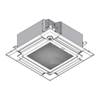
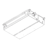
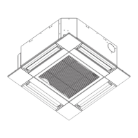
Identifies and describes the various parts of the indoor unit.
Details the functions and features of the wired remote controllers.
Explains the layout, buttons, and operation of the wired remote controller interface.
Explains the meaning of various icons and modes displayed on the remote controller screen.
Illustrates the hierarchical structure of the remote controller's main menu system.
Details the options available within the maintenance and service menus of the remote controller.
Provides a comprehensive list of settings and functions accessible via the main menu.
Details various sub-menus including initial settings, display, operation, maintenance, and service options.
Explains the layout, buttons, and display icons of the wireless remote controller.
Details button functions, operation modes, and settings for the wireless remote controller.
Presents technical specifications for indoor unit models, including capacity and dimensions.
Lists electrical parts with their symbols, specifications, and ratings.
Details the location and procedure for installing the fresh air intake.
Provides data on fresh air intake volume and its relationship with static pressure.
Explains how to connect and operate the unit with an optional duct fan.
Provides instructions on how to set and fix the horizontal vane position.
Shows detailed dimensional drawings and outlines for the indoor units.
Illustrates the electrical wiring connections for the indoor units.
Presents a schematic diagram of the unit's refrigerant system components.
Details the control logic and operation for the cooling mode.
Explains the control mechanisms for the drain pump and the up/down vane movement.
Provides further details on heat operation modes and introduces automatic cool/heat changeover.
Describes control functions that operate when the unit is in a stopped state.
Lists error codes that appear during test run and their corresponding countermeasures.
Provides procedures and check points for testing various components of the unit.
Provides resistance values for thermistors at different temperatures.
Explains the operation and connection of the linear expansion valve.
Details output pulse signals and how they affect linear expansion valve operation.
Covers common problems and countermeasures for the linear expansion valve mechanism.
Provides methods for checking the DC fan motor and indoor controller board.
Explains the functions of various DIP switches on the indoor controller board.
Details specific functions controlled by SW21, SW22, and the SWE connector for test run.
Illustrates test points on the indoor controller board for diagnostics.
Step-by-step instructions for removing the air intake grille and air filter.
Detailed steps for safely removing the unit's front panel and associated components.
Instructions for safely removing electrical components like the controller board and terminal blocks.
Procedure for detaching and removing the room temperature sensor.
Steps for removing the drain pan and associated parts.
Procedure for removing the pipe temperature sensors (TH22, TH23).
Detailed steps for removing the fan motor, including the turbo fan.
Instructions for removing the drain pump and float switch assembly.
Procedure for detaching and removing the unit's heat exchanger assembly.