-
43
-
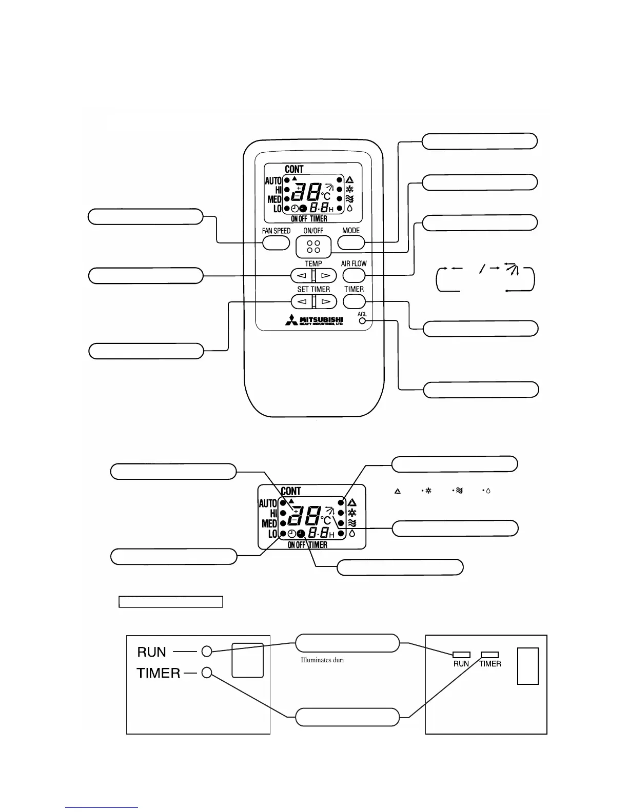
FAN SPEED button
Each time the button is pushed, the¡
indicator is switched over in turn.
TEMPERATURE button
This button sets the room temperature.
SET TIMER button
This button sets the ON timer and OFF
timer times.
OPERATION MODE select button
Each time the button is pushed, the¡
indicator is switched over in turn.
ON/OFF button
Press for starting operation, press again
for stopping.
AIRFLOW button
This button changes the flap mode. When
pressed, this button changes the mode in
the following order:
or
(AUTO) (SWING)
no indication
(SWING STOPPED)
TIMER button
This button changes the selection of ON
timer/OFF timer operation and normal
operation.
RESET switch
Switch for resetting microcomputer.
¡ The above illustration shows all controls, but in
practice only the relevant parts are shown.
S Indication section
TEMPERATURE Indicator
Indicates set temperature.
(Does not indicate temperature when
operation mode is on AUTO)
FAN SPEED Indicator
Indicates set air flow rate with¡lamp
OPERATION MODE Indicator
Indicates selected operation with¡lamp
AIR FLOW Indicator
Shows selected flap mode.
TIMER Indicator
Unit indication section
(Auto) (Cool) (FAN) (Dry)
¡ 06, 07, 09 type
RUN
TIMER
TIMERRUN
Illuminates during operation.
Illuminates during TIMER operation.
RUN light (green)
TIMER light (yellow)
¡ 12 type
4 OUTLINE OF OPERATION CONTROL BY MICROCOMPUTER
(1) Operation control function by remote controller
 Loading...