Do you have a question about the Mitsubishi 10 and is the answer not in the manual?
| Brand | Mitsubishi |
|---|---|
| Model | 10 |
| Category | Air Conditioner |
| Language | English |
Improved sensible cooling capacity due to optimized heat exchanger design.
Effective heating performance even at low outdoor temperatures for PRH series.
Enhanced EER achieved through revised design and high-quality manufacturing.
Belt-driven supply air fans allow accurate airflow matching via pulley adjustments.
Single unit configuration simplifies installation, omitting refrigeration work.
Optional accessory enables cooling operation at low outdoor temperatures.
Flexible control configurations for integration with building management systems.
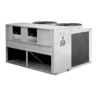
Factory assembled, tested, and charged units designed for outdoor installation.
Detailed technical specifications for unit components like coils, compressors, and fans.
Technical drawing and specifications for the V-belt groove shape.
Dimensions and specifications for motor pulley bosses based on motor capacity.
Detailed dimensions and fixing specifications for the unit's motors.
Standard wiring diagram for PR-5, 8, and 10YC models.
Standard wiring diagram for PR-15 and 20YC models.
Wiring diagram for PR-5, 8, 10YC with special order K control.
Wiring diagram for PR-5, 8, 10YC with special order low temperature option.
Wiring diagram for PR-15, 20YC with special order low temperature option.
Standard wiring diagram for PRH-5, 8, 10YA models.
Standard wiring diagram for PRH-15, 20YA models.
Wiring diagram for PRH-5, 8, 10YA with special order K control.
Wiring diagram for PRH-5, 8, 10YA with K control and low temp options.
Wiring diagram for PRH-15, 20YA with special order low temperature option.
Wiring diagram for PRH-15, 20YA with K control and low temp options.
Flowchart detailing the electrical operation sequence for PR-5, 8, 10YC units.
Flowchart detailing the electrical operation sequence for PRH-5, 8, 10YA units.
Flowchart detailing the electrical operation sequence for PR-15, 20YC units.
Flowchart detailing the electrical operation sequence for PRH-15, 20YA units.
Schematic diagram of the refrigerant cycle for the PR-5YC model.
Schematic diagram of the refrigerant cycle for PR-8, 10, 15, 20YC models.
Schematic diagram of the refrigerant cycle for the PRH-5YA model.
Schematic diagram of the refrigerant cycle for PRH-8, 10, 15, 20YA models.
Schematic diagram of the refrigerant cycle for the PRH-5YA-L model.
Schematic diagram of the refrigerant cycle for PRH-8, 10,15,20YA-L models.
Recommended minimum clearances around the unit for proper operation and service.
Guidance on using roof curbs and sealing for secure unit installation on roofs.
Instructions for connecting supply and return air ducts, including sealing and insulation.
Requirements for condensate drain fitting, trap, incline, and insulation.
Instructions for connecting the unit's power supply wiring to the control box terminals.
Checklist of essential checks after installation, including unit fixing and wiring.
Procedures for conducting a trial operation, including electrical resistance checks.
Pre-operation checks to ensure proper airflow and grounding.
Important points to observe to prevent failures and breakdowns during operation.
Guidelines for cleaning air filters and panels for optimal performance and durability.
Steps to follow before starting operation after a period of prolonged shutdown.
Procedures for preparing the unit for storage after the usage season.
Common issues, their possible causes, and recommended remedies for operational problems.