4 - 4
MELSEC-A
4 INSTALLATION, WIRING AND MAINTENANCE OF THE PRODUCT
No. Name Details
1) 17-segment LED
2) Axis display LED (AX1 to 3)
Display the operating status (1)) of the target axis (2)) for that axis.
RUN : The LED corresponding to the operating axis flickers.
TEST : The LEDs of all axes turn ON.
IDL : OFF
ERR : The LED corresponding to the axis in error flickers.
3) Mode switch
Each time this switch is pressed, the details displayed on "1) 17-segment LED" and
"2) Axis display LED" will change.
[Display details]
Operation monitor 1 Operation monitor 2
Internal information 1
Internal information 2
Input information n
(Refer to section "13.4 LED display function" for details on the displayed
information.)
4) Module version label
This label indicates the module's software version and hardware version.
(Example)
Indicates that software version is "B".
Indicates that hardware version is "A".
A B
5)
Peripheral device connection
connector
Connector for connecting with peripheral device.
6)
External device connection
connector
Connector for connecting mechanical system input and manual pulse generator.
7)
SSCNET connection
connector
SSCNET connector for connection with the servo amplifier.
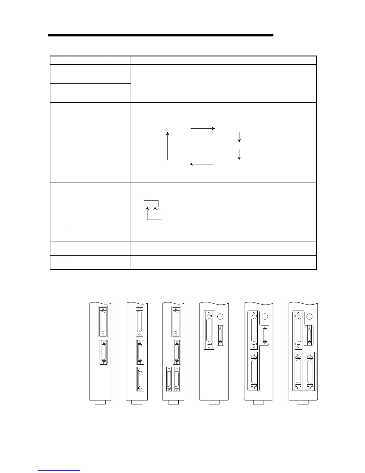
Each AD75 interface is as shown below.
A1SD75M1AD75M1 AD75M2 AD75M3 A1SD75M2 A1SD75M3
RS-422
AX1
AX2
AX3
RS-422
AX1
AX2
RS-422
AX1
A1SD75M2
AX2
RS-422
AX1
MODE
A1SD75M1
RS-422
MODE
AX1
A1SD75M3
AX3AX2
RS-422
AX1
MODE
 Loading...


