Do you have a question about the Mitsubishi FX2N and is the answer not in the manual?
Guidelines for user safety and protection when using the FX2N-32DP-IF unit.
Explanation of symbols used in the manual for warnings and important notes.
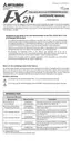
Key features and capabilities of the FX2N-32DP-IF Profibus-DP Interface Unit.
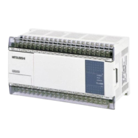
Physical dimensions and identification of the unit's components and connectors.
Overview of system configuration, including network setup and connected devices.
Instructions for physically installing the unit within an enclosure for optimal operation.
Important precautions and step-by-step procedures for electrical wiring.
Specifics for connecting the unit to the Profibus-DP network.
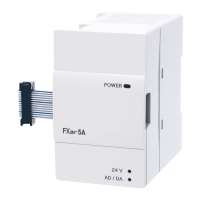
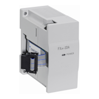
Wiring instructions for connecting extension I/O units and special function blocks.
Environmental, physical, and electrical characteristics of the unit.
Details on power supply requirements, including voltage, current, and ratings.
Technical performance data, including communication speed and I/O handling.
Overview of data registers used for input, output, and parameter data exchange.
Information on special devices used for monitoring and diagnostics.
Details on error status flags and their meanings for troubleshooting.
Procedure for setting the Profibus-DP slave address using DIP switches.
Illustrative example of setting a specific slave address for the unit.
Guidelines for defining and using user parameters for configuration.
Methods for configuring slave parameters using GSD files or programming tools.
Structure of diagnostic messages sent from the 32DP-IF to the DP-master.
List of diagnostic messages and their corresponding meanings and error codes.
Initial troubleshooting steps and checks before detailed diagnostics.
Interpreting the status of the POWER, RUN, BF, and DIA LEDs.
Checking error status bits in D8029 and related error codes for troubleshooting.
Default user parameter settings applied after the unit is powered on.
How data is exchanged when using default parameter settings.
General examples of user parameter configuration for various modules.
Procedure for adjusting offset and gain parameters for specific modules.
Steps to restore the unit's parameters to their default values.
| Type | PLC |
|---|---|
| Series | FX2N |
| Manufacturer | Mitsubishi Electric |
| Power Supply | 100-240VAC or 24VDC |
| Program Capacity | 8, 000 steps |
| I/O Points | Up to 256 points |
| Expansion | Yes, via expansion modules |
| Instruction Set | Basic and advanced instructions |
| Output Type | Relay or Transistor |
| Humidity | 5 to 95% RH, non-condensing |
| Communication | RS-422, RS-485 |
| Input Points | Up to 128 points |
| Output Points | Up to 128 points |
| Execution Speed | 0.08 µs per instruction |
| Programming Language | Instruction List |
| Data Memory | 8, 000 words |
| Operating Temperature | 0 to 55°C |
| Storage Temperature | -20°C to 70°C |