FX
2N
-4DA SPECIAL FUNCTION BLOCK
USER’S GUIDE
JY992D65901C
This manual contains text, diagrams and explanations which will guide the reader in the correct installation
and operation of the FX
2N
-4DA special function block and should be read and understood before
attempting to install or use the unit.
Further information can be found in the FX PROGRAMMING MANUAL(
ΙΙ
) and FX
0N
/FX
1N
/FX
2N
/FX
2NC
/
FX
3U
SERIES HARDWARE MANUAL.
Guidelines for the Safety of the User and Protection of the FX
2N
-4DA
special function block.
This manual should be used by trained and competent personnel. The definition of such a person or
persons is as follows:
a) Any engineer using the product associated with this manual, should be of a competent nature,
trained and qualified to the local and national standards. These engineers should be fully aware of
all aspects of safety with regards to automated equipment.
b) Any commissioning or service engineer must be of a competent nature, trained and qualified to
the local and national standards.
c) All operators of the completed equipment should be trained to use this product in a safe and
coordinated manner in compliance to established safety practices.
Note:
The term ‘completed equipment’ refers to a third party constructed device which contains or uses
the product associated with this manual.
Notes on the Symbols Used in this Manual
At various times throughout this manual certain symbols will be used to highlight points of information
which are intended to ensure the users personal safety and protect the integrity of equipment.
1) Indicates that the identified danger
WILL
cause physical and property damage.
2) Indicates that the identified danger could
POSSIBLY
cause physical and property
damage.
• Under no circumstances will Mitsubishi Electric be liable or responsible for any consequential damage
that may arise as a result of the installation or use of this equipment.
• All examples and diagrams shown in this manual are intended only as an aid to understanding the
text, not to guarantee operation. Mitsubishi Electric will accept no responsibility for the actual use of
the product based on these illustrative examples.
• Owing to the very great variety in possible application for this equipment, you must satisfy yourself as
to its suitability for your specific application.
1. INTRODUCTION
• The FX
2N
-4DA analog special function block has four analog output channels. The output channels
take a digital value and output an equivalent analog signal. This is known as a D/A conversion. The
FX
2N
-4DA has a maximum resolution of 12 bits.
• The selection of voltage or current based input/output is by user wiring. Analog ranges of -10 to 10V
DC (resolution: 5mV), and/or 0 to 20mA (resolution: 20
µ
A) maybe selected independently for each
channel.
• The FX
2N
-4DA can connected to the FX
0N
/FX
1N
/FX
2N
/FX
2NC
/FX
3U
series Programmable Controllers
(PLC).
• Data transfer between the FX
2N
-4DA and the main unit is completed buffer memory exchange. There
are 32 buffer memories (each of 16 bits) in the FX
2N
-4DA.
• The FX
2N
-4DA occupies 8 I/O points on the FX
2N
expansion bus. The 8 I/O points can be allocated
from either inputs or outputs. The FX
2N
-4DA draws 30mA from the 5V rail of the main unit or powered
extension unit.
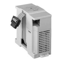
2. EXTERNAL DIMENSIONS AND PARTS
3. CONNECTION WITH PLC
The FX
2N
-4DA unit can be connected to the PLCs as follows. Resrictions apply to the maximum number
of connectable units, depending on the DC24V/DC5V Power Supply capacities and the Main Unit/Special
Function Unit types. For details, refer to the respective PLC manual.
FX
2N
/FX
3U
: The maximum connectable units is 8.
FX
2NC
: The maximum connectable units is 4.
To connect the FX
2N
-4DA with the FX
2NC
main unit, FX
2NC
-CNV-IF is required.
FX
1N
: The maximum connectable units is 8.
FX
0N
: The maximum connectable units is 4.
4. WIRING
The terminal layout shown below may differ from the actual layout. For the correct terminal layout, refer to
section 2 External Dimensions and Parts.
P O W E R
D / A
2 4 V
F X 2 N - 4 D A
I +
V +
I +
V I -
C H 4
C H 3
C H 2
C H 1
V +
I +V +
I +
V +
2 4 +
2 4 -
V I -
V I -
V I -
8
9
1
4 ( 0 . 1 6 )
2
5 5 ( 2 . 1 7 )
9 0 ( 3 . 5 4 )
8 7 ( 3 . 4 3 )
5 5 ( 2 . 1 7 )
8 0 ( 3 . 1 5 )
9 ( 0 . 3 5 )
7
6
5
4
3
4 ( 0 . 1 6 )
C H 1
V +
2 4 +
2 4 -
V I -
Dimensions: mm (inches)
• Weight: Approx. 0.3 kg (0.66 lbs) • Accessory: Special block number label
c
Extension cable
d
Power indicator lamp (LED)
5 V power is supplied from the
programmable controller to light this
indicator lamp.
e
Power supply terminals
(Screw terminal: M3 (0.12))
f
Analog output terminals
(Screw terminals: M3 (0.12))
g
24V power indicator lamp (LED) 24V DC
power is supplied to the terminals of the
FX
2N
-4DA to light this indicator lamp.
h
D/A conversion indicator lamp (LED)
Flashes at a high speed if D/A conversion
is performing without a problem.
i
Hook for DIN rail
j
Groove for DIN rail mounting
(Width of DIN rail: 35 mm 1.38")
k
Hole for direct mounting (2-
φ
4.5) (0.18)
6 . 2 m m
( 0 . 2 4 i n c h e s )
o r l e s s
F O R M 3 ( 0 . 1 2 )
Handling of crimp-style terminal
• Be sure to use the crimp-style terminals that satisfy the
dimensional requirements shown in the left figure.
• Apply 0.5 to 0.8 N
⋅
m torque to tighten the terminals. Firmly
tighten the terminals to prevent abnormal operation.
*6
DC24V–10%200mA
*4
D grounding
(100
Ω
or less)
PLC
Extension cable
24+
24-
FX -4DA
2N
DC/DC
converter
AG
+15V
+15V
CH1
CH2
V+
I +
VI -
V+
I +
VI -
*2
*5
*2
Mixed output from the same channel is not possible.
*1
*7
*3 Inverter,etc.
Recorder,etc.
*1
*1: Use a twisted pair shielded cable for the
analog output. This cable should be
wired away from power lines or any other
lines which could induce noise.
*2: Apply 1-point grounding at the load side
of the output cable (grounding: 100
Ω
or
less).
*3: If electrical noise or a voltage ripple
exists at the output, connect a smoothing
capacitor of 0.1 to 0.47
µ
F, 25V.
*4: Connect the terminal on the FX
2N
-4DA with
the terminal on the main unit of the PLC.
*5: Shorting the voltage output terminal or connecting
the current output load to the voltage output
terminal may damage the FX
2N
-4DA.
*6: The 24V DC service power of the PLC can also be
used.
*7: Do not connect any unit to the unused terminal
•
5. SPECIFICATIONS
5.1 General specifications
5.2 Performance specification
6. ALLOCATION OF BUFFER MEMORIES (BFM)
Data is transmitted between the FX
2N
-4DA and the main unit via buffer memories (16-bit 32-point RAM).
Buffer memories marked “W” can
be written to using the T0
instruction in the main unit.
The status of BFM #0, #5, and #21,
(marked E) will be written to
EEPROM, therefore the set values
will be retained even after turning
off the power.
1) [BFM #0] Output mode select: The value of BFM #0 switches the analog output between voltage and
current on each channel. It takes the form of a 4 digit hexadecimal number. The first digit will be the
command for channel 1 (CH1), and the second digit for channel 2 (CH2) etc. The numeric values of
these four digits respectively represent the following items:
O = 0:Sets the voltage output mode (-10 V to +10 V).
O = 1:Sets the current output mode (+4 mA to 20 mA).
O = 2:Sets the current output mode (0 mA to +20 mA).
Switching the output mode resets the I/O characteristics to the factory-default characteristics. Refer to the
performance specifications described in section 4.
Example: H2110 CH1 : Voltage output (-10 V to +10 V)
CH2 and CH3 : Current output (+4 mA to +20 mA)
CH4 : Current output (0 mA to +20 mA)
2) [BFM #1, #2, #3 and #4]: Output data channels CH1, CH2, CH3, and CH4
BFM #1: Output data of CH1 (Initial value: 0)BFM #2: Output data of CH2 (Initial value: 0)
BFM #3: Output data of CH3 (Initial value: 0)BFM #4: Output data of CH4 (Initial value: 0)
Item Specification
General specifications Same as those for the main unit
Dielectric withstand voltage 500V AC, 1min (between all terminals and ground)
Item Centigrade Fahrenheit
Analog output range
-10V DC to +10V DC (External load
resistance: 2k
Ω
to 1M
Ω
).
DC 0mA to +20mA (External load
resistance: 500
Ω
).
Digital input
16 bits, binary, with sign
(Effective bits for numeric value: 11 bits
and sign bit (1 bit))
16 bits, binary, with sign
(Effective bits for numeric value: 10 bits)
Resolution 5mV (10V
×
1/2000) 20
µ
A (20mA
×
1/1000)
Total accuracy ±1% (at full scale of +10V) ±1% (at full scale of +20mA)
Conversion speed
2.1ms for 4 channels (Change in the number of channels used will not change
the conversion speed.)
Isolation
Photo-coupler isolation between analog and digital circuits.
DC/DC converter isolation of power from main unit.
No isolation between analog channels.
External power supply 24V DC ±10% 200mA
Number of occupied
I/O points
The analog block occupies 8 I/O points.
(can be either inputs or outputs)
Power consumption 5V, 30mA (Internal power supply from MPU or powered extension unit)
I/O characteristics
(Default: mode 0)
Follow the procedure
described in section 8
to change
Mode 0 (Voltage
output: -10V to
+10V)
At load resistance
of 10k
Ω
Mode 1 (Current
output: +4mA to
+20mA)
At load resistance
of 250
Ω
Mode 2 (Current
output: 0mA to
+20mA)
At load resistance
of 250
Ω
Command sent from the programmable
controller can change the mode. The
voltage/current output mode selected
will determine the output terminals
used.
A n a l o g o u t p u t
D i g i t a l i n p u t
+ 1 0 V
+ 1 0 . 2 3 5 V
- 2 , 0 0 0
+ 2 , 0 0 0
- 1 0 V
- 1 0 . 2 4 V
- 2 , 0 4 8
+ 2 , 0 4 7
A n a l o g
o u t p u t
+ 4 m A
D i g i t a l i n p u t
+ 2 0 m A
0
+ 1 , 0 0 0
A n a l o g
o u t p u t
D i g i t a l i n p u t
+ 2 0 m A
0
+ 1 , 0 0 0