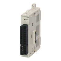
Do you have a question about the Mitsubishi FX3U-4AD and is the answer not in the manual?
Precautions for designing systems to ensure safe operation during external power supply problems or PLC failure.
Precautions to take before and during wiring work to prevent electric shock or product damage.
Precautions for safe startup, operation, and maintenance of the PLC and associated equipment.
Describes the three types of analog control: voltage/current input, voltage/current output, and temperature sensor input.
Provides general specifications like ambient temperature, humidity, vibration, and shock resistance.
Details performance specifications for analog input/output products, including resolution and accuracy.
Illustrates the terminal arrangement for various analog modules.
Shows examples of power supply circuits and cautions for connecting power to analog modules.
Provides guidelines for proper grounding to ensure system stability and prevent noise interference.
Explains unit number assignment and provides an overview of buffer memory structure.
Provides detailed information on various buffer memory areas and their functions.
Demonstrates a program that utilizes the analog data averaging time for stable data acquisition.
Shows examples of programs utilizing functions like error detection and status transfer.
Explains how to reset the analog module to its factory default settings using a program.
Verifies PLC version compatibility required for the analog module.
Provides steps to check power connection, analog input lines, and current input mode wiring.
Explains how to interpret error status bits in BFM #29 to diagnose issues.
Describes the purpose and basic operation of the PID instruction for control systems.
Details the instruction format, parameter settings, and target devices for PID control.
Explains the auto-tuning function to automatically set PID control constants for optimal performance.
| Model | FX3U-4AD |
|---|---|
| Type | Analog Input Module |
| Input Channels | 4 |
| Input Type | Voltage or Current |
| Current Input Range | 4 to 20 mA |
| Resolution | 12 bits |
| Insulation Method | Photocoupler insulation |
| Power Supply | 5V DC (supplied from the base unit) |
| Voltage Input Range | -10 to +10V DC |


 Loading...