FX2N-32DP-IF Profibus-DP Interface Unit Advanced Devices 4
4-5
4.2.2 Profibus-DP Network Status (M8020 ~ M8039 and D8020 ~ D8039)
Note 1: Swap byte order
Some DP-masters handle lower bytes and higher bytes of a word in a reverse order than the 32DP-
IF. To enable the module to communicate with these masters, bit 0 of data register D8021 can be set.
If bit 0 is “1”, the low order byte and the high order byte of each user data word and of the user spe-
cific diagnosis will be swapped. Bit 0 of D8021 can also be set or reset by the second user defined
parameter byte received from a master. The default value after power up is “0”.
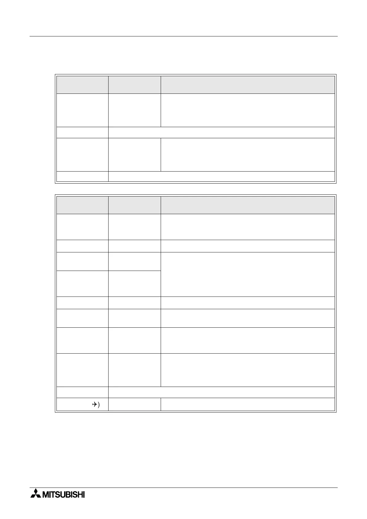
Table 4.5:Special Auxiliary Relays (M8020 ~ M8039)
Diagnostic
Device
Name Description
M8020 Setting parameter
When this bit is changed from OFF to ON, the parameter D200
~ D299 (made by the programming tool) is written to special
function blocks’ BFM. After the write is completed, this bit is
turned automatically to OFF.
M8021 ~ M8033 Reserved
M8034 All output disable
All physical switch gear for activating outputs is disabled. How-
ever, for debugging purposes the logical state of these outputs
(D100 ~ D199) can be set, but remain disabled in the actual
module.
M8035 ~ M8039 Reserved
Table 4.6:Special Data Registers (D8020 ~ D8039)
Diagnostic
Device
Name Description
D8020
(
)
Data exchange
status
Data register D8020 contains a status bit for data exchange.
If this is “1”, 32DP-IF is in data exchange mode.
If this is “0”, 32DP-IF is not in data exchange mode.
D8021
(
)
Swap byte order See note 1.
D8022
(
)
Length of input
(sent) data in byte
The values held in these devices are copied from the input data
length and output data length setting in the DP-master.
D8023
(
)
Length of output
(received) data in
byte
D8024
(
)
Baud rate See note 2.
D8025
(
)
Communication
status
See note 3.
D8026
(
)
Profibus module
ID (PNO ID code)
PNO-Nr.F232 (Hex)
(This number contains the Profibus module ID number for the
32DP-IF.)
D8027
(
)
Slave address
The slave address is set only by the 32DP-IF’s DIP switches.
The slave address value is 0 to 126. The address change by a
Profibus-DP Class 2 master via the network or by a program-
ming device is not supported.
D8028 Reserved
D8029
(
) (
)
Error status See note 4.

 Loading...