5 - 44
MELSEC-A
5 DATA USED FOR POSITIONING CONTROL
Setting value, setting range
Setting value buffer
memory address
Item
Value set with peripheral
device
Value set with sequence
program
Default
value
Axis 1 Axis 2 Axis 3
Pr.41
Positioning complete
signal output time
0 to 65535 (ms)
0 to 65535 (ms)
0 to 32767 :
Set as a decimal
32768 to 65535:
Convert into hexadecimal
and set
300 59 209 359
Pr.42
Allowable circular
interpolation error
width
The setting value range differs depending on the "
Pr.1
Unit setting".
Here, the value within the [Table 1] range is set.
[Table 1] on right page
100
60
61
210
211
360
361
0 : External positioning start 0
1 : External speed change
request
1
Pr.43
External start function
selection
2 : Skip request 2
0 62 212 362
0 : Positioning address pass
mode
0
Pr.44
Near pass mode
selection for path
control
1 : Near pass mode 1
0 66 216 366
Pr.150
Setting for the restart
allowable range when
servo OFF to ON
0 to 163840 (pulse) 0 to 163840 (pulse) 0
64
65
214
215
364
365
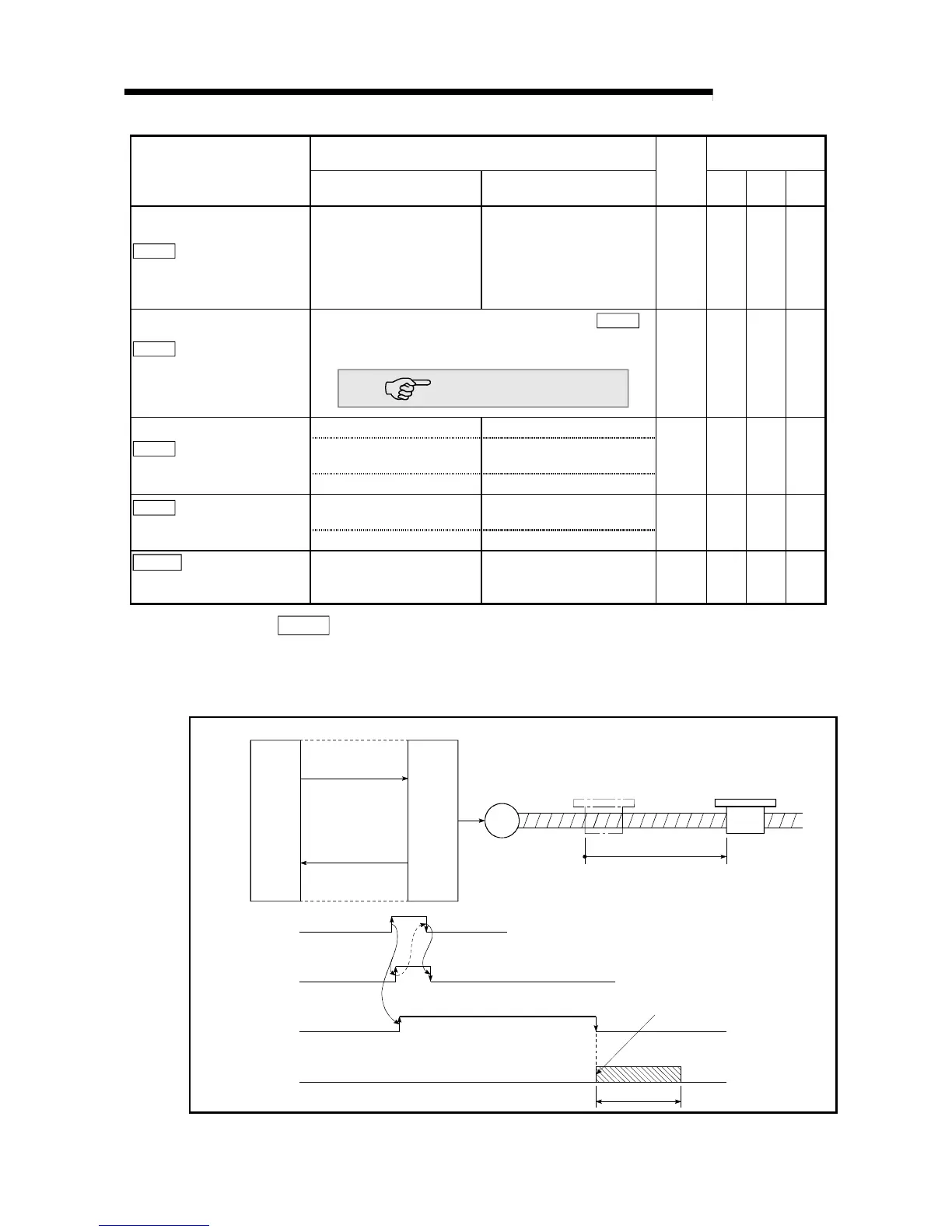
Pr.41
Positioning complete signal output time
Set the output time of the positioning complete signal [X7, X8, X9] output from the
AD75.
Positioning complete refers to the state in which the positioning operation
complete has completed, and the specified dwell time has passed.
M
AD75
[Y10, Y11, Y12]
PLC
PLC CPU
Positioning start signal
Positioning
complete signal
[X7, X8, X9]
Positioning
Positioning
start signal
Start complete
signal
BUSY signal
Positioning
complete signal
Positioning complete signal
(after dwell time has passed)
Output time
Positioning complete signal output time

 Loading...


