5 - 84
MELSEC-A
5 DATA USED FOR POSITIONING CONTROL
Servo amplifier
side parameter
Setting value, setting range
Setting value buffer
memory address
Item
No.
Abbre-
viation
Value set with peripheral
device
Value set with sequence
program
Default
value
Axis 1 Axis 2 Axis 3
0 : Servomotor speed
0
H
/
0
H
1 : Torque
1
H
/
1
H
2 : Servomotor speed (+)
2
H
/
2
H
3 : Torque (+)
3
H
/
3
H
4 : Current command
4
H
/
4
H
5 : Command speed
5
H
/
5
H
6 : Droop pulse 1/1
6
H
/
6
H
7 : Droop pulse 1/16
7
H
/
7
H
8 : Droop pulse 1/64
8
H
/
8
H
9 : Droop pulse 1/256
9
H
/
9
H
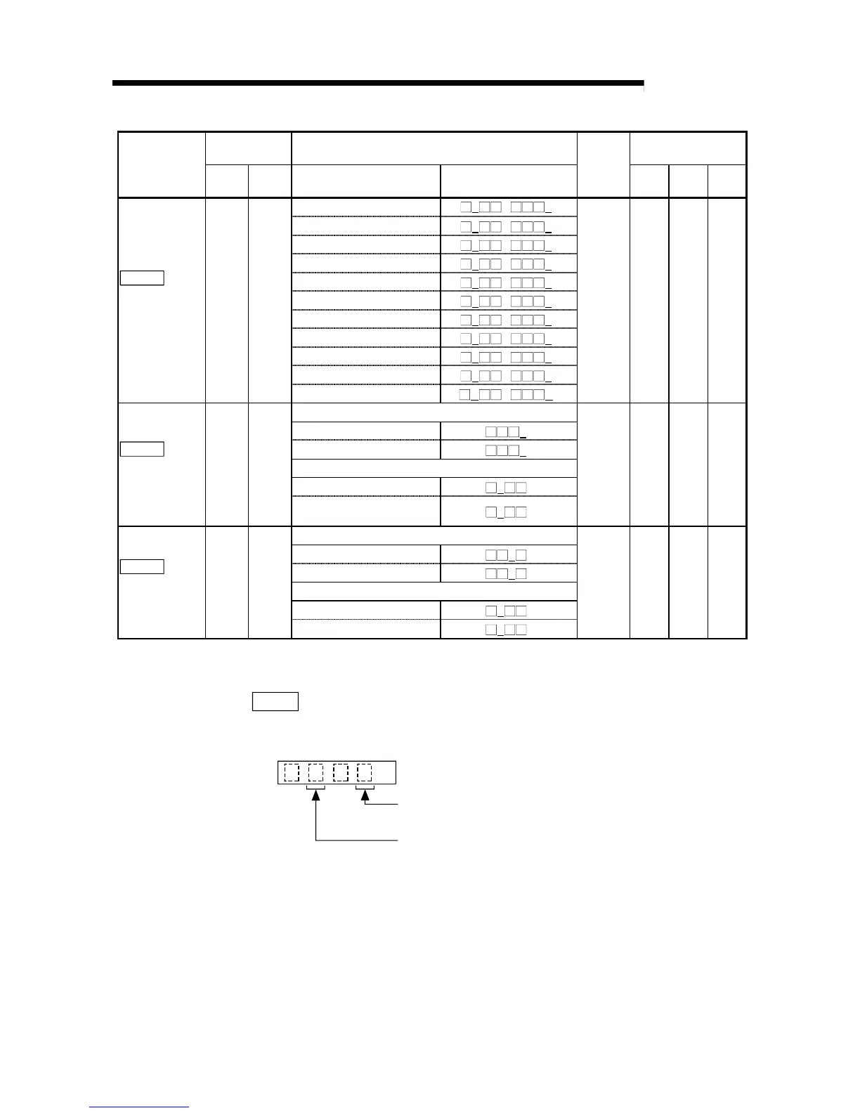
Pr.122
Monitor output
mode
selection
No.22 MOD
A : Droop pulse 1/1024
A
H
/
A
H
0001
H
122 272 422
Amplifier EMG selection
0 : Valid
0
H
1 : Invalid
1
H
Serial encoder cable selection
0 : 2-wire
0
H
Pr.123
Option
function 1
No.23 *OP1
1 : 4-wire (Supports long
distance cables)
1
H
0000
H
123 273 423
Slight vibration suppression function selection
0 : Invalid
0
H
1 : Valid
1
H
Motor-less operation selection
0 : Invalid
0
H
Pr.124
Option
function 2
No.24 *OP2
1 : Valid
1
H
0000
H
124 274 424
* This parameter is made valid when the servo amplifier is powered OFF, then ON again after it has been transferred
from the AD75 to the servo amplifier.
Pr.122
Monitor output mode selection
Select the signals to be output from the analog monitor CH1 and CH2 of the servo
amplifier.
Monitor output 1 selection
H
Monitor output 2 selection
00
Set any of 0 to A. (Refer to the settings of the following monitor output 1)
0: Servomotor speed
1: Torque
2: Servomotor speed (+)
3: Torque (+)
4: Current command
5: Command speed
6: Droop pulse 1/1
7: Droop pulse 1/16
8: Droop pulse 1/64
9: Droop pulse 1/256
A: Droop pulse 1/1024

 Loading...


