5 - 94
MELSEC-A
5 DATA USED FOR POSITIONING CONTROL
Servo amplifier
side parameter
Setting value, setting range
Setting value buffer
memory address
Item
No.
Abbre-
viation
Value set with peripheral
device
Value set with sequence
program
Default
value
Axis 1 Axis 2 Axis 3
Notch frequency
0 : Invalid
00
H
1 : 4500
01
H
2 : 2250
02
H
3 : 1500
03
H
4 : 1125
04
H
5 : 900
05
H
6 : 750
06
H
7 : 642.9
07
H
–
08 to
1F
H
Notch depth
0 : -40db
0
H
Pr.118
Machine
resonance
suppression
filter 1
No.18 NCH
–
1
to
3
H
0000
H
118 268 418
Pr.119
Feed forward
gain
No.19 FFC 0 to 100 (%) 0 to 100 (%) 0 119 269 419
Pr.120
In-position
range
No.20 INP 0 to 50000 0 to 50000 100 120 270 420
Pr.121
Solenoid
brake output
No.21 MBR 0 to 1000 (ms) 0 to 1000 (ms) 100 121 271 421
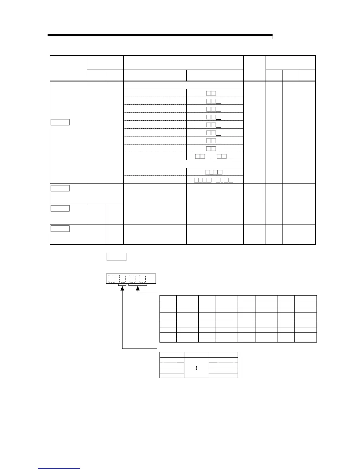
Pr.118
Machine resonance suppression filter 1
Set the machine resonance suppression filter 1 (notch frequency, notch depth).
H
Notch frequency
0
00
01
02
03
04
05
06
07
08
09
0A
0B
0C
0D
0E
0F
10
11
12
13
14
15
16
17
18
19
1A
1B
1C
1D
1E
1F
Invalid
4500
2250
1500
1125
900
750
642.9
562.5
500
450
409.1
375
346.2
321.4
300
281.3
264.7
250
236.8
225
214.3
204.5
195.7
187.5
180
173.1
166.7
160.1
155.2
150
145.2
Setting Setting Setting SettingFrequency Frequency Frequency Frequency
Notch depth
0
1
2
3
Gain
-40dB
-14dB
-8dB
-4dB
Depth
Setting
Deep
shallow
On the peripheral device, any of only the notch frequencies "00" to "07" can be set
as the notch filter selection of the MR-J2-B.
(Since the setting is made as the MR-J2-B, the screen display differs from the above.)
On the peripheral device, the notch depth cannot be set. (It is set to the initial
setting "0".)
When setting any of notch frequencies "08" to "1F" and notch depths "1" to "3", set
this parameter in the sequence program.

 Loading...


