5 - 96
MELSEC-A
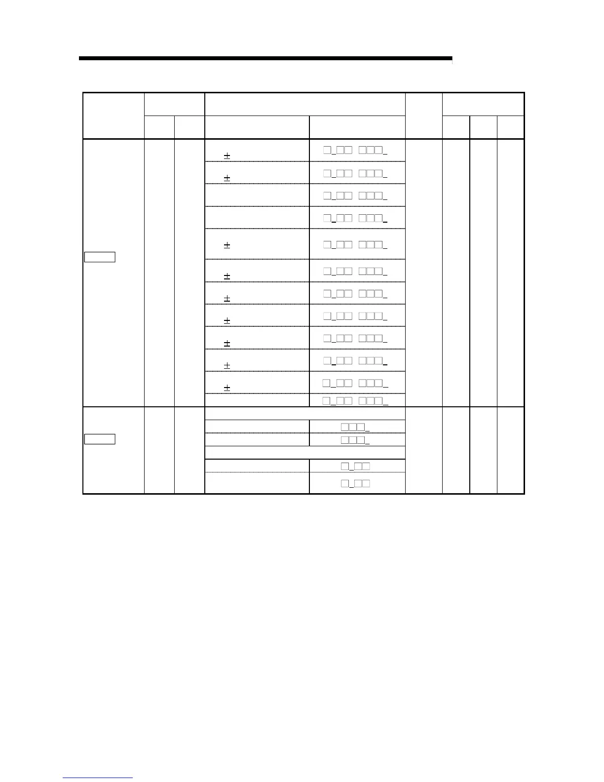
5 DATA USED FOR POSITIONING CONTROL
Servo amplifier
side parameter
Setting value, setting range
Setting value buffer
memory address
Item
No.
Abbre-
viation
Value set with peripheral
device
Value set with sequence
program
Default
value
Axis 1 Axis 2 Axis 3
0 : Servomotor speed
( 8V/max. speed)
0
H
/
0
H
1 : Torque
( 8V/max. torque)
1
H
/
1
H
2 : Servomotor speed
(+8V/max. speed)
2
H
/
2
H
3 : Torque
(+8V/max. torque)
3
H
/
3
H
4 : Current command
( 8V/max. current
command)
4
H
/
4
H
5 : Command speed
(
8V/max. speed)
5
H
/
5
H
6 : Droop pulse
(
10V/128 pulses)
6
H
/
6
H
7 : Droop pulse
( 10V/2048 pulses)
7
H
/
7
H
8 : Droop pulse
(
10V/8192 pulses)
8
H
/
8
H
9 : Droop pulse
(
10V/32768 pulses)
9
H
/
9
H
A : Droop pulse
( 10V/131072 pulses)
A
H
/
A
H
Pr.122
Monitor output
mode
selection
No.22 MOD
–
B
H
/
B
H
0001
H
122 272 422
Amplifier EMG selection
0 : Valid
0
H
1 : Invalid
1
H
Serial encoder cable selection
0 : 2-wire
0
H
Pr.123
Option
function 1
No.23 *OP1
1 : 4-wire (Supports long
distance cables)
1
H
0000
H
123 273 423
* This parameter is made valid when the servo amplifier is powered OFF, then ON again after it has been transferred
from the AD75 to the servo amplifier.

 Loading...


