6 - 3
MELSEC-A
6 SEQUENCE PROGRAM USED FOR POSITIONING CONTROL
(b) With the 3-axis module, the number of times the FROM/TO command, the
DFRO/DTO command, and the command using the special function module
device are executed changes depending on the function to be executed.
•
When carrying out circular interpolation control and S-pattern
acceleration/deceleration : 4 times/axis
•
When CHG input is input simultaneously for two axes during
speed/position changeover control : 4 times/axis
•
When not carrying out the above control : 10 times/axis
Circular
interpolation
control
S-pattern
acceleration/
deceleration
Speed/position changeover
control (CHG input
simultaneously for two axes)
Control other
than that on left
A1SD75M1
AD75M1
10 times/axis 10 times/axis 10 times/axis 10 times/axis
A1SD75M2
AD75M2
10 times/axis 10 times/axis 10 times/axis 10 times/axis
A1SD75M3
AD75M3
4 times/axis 4 times/axis 4 times/axis 10 times/axis
(5) Restrictions to speed change execution interval
Provide an interval of 100ms or more when changing the speed with the AD75.
(6) Process during overrun
Overrun is prevented with the AD75's upper and lower stroke limit. However, this
applies only when the AD75 is operating correctly. In terms of the entire system's
safety, it is recommended to provide a boundary limit switch and provide an
external circuit that will power OFF the motor when the limit switch operates.
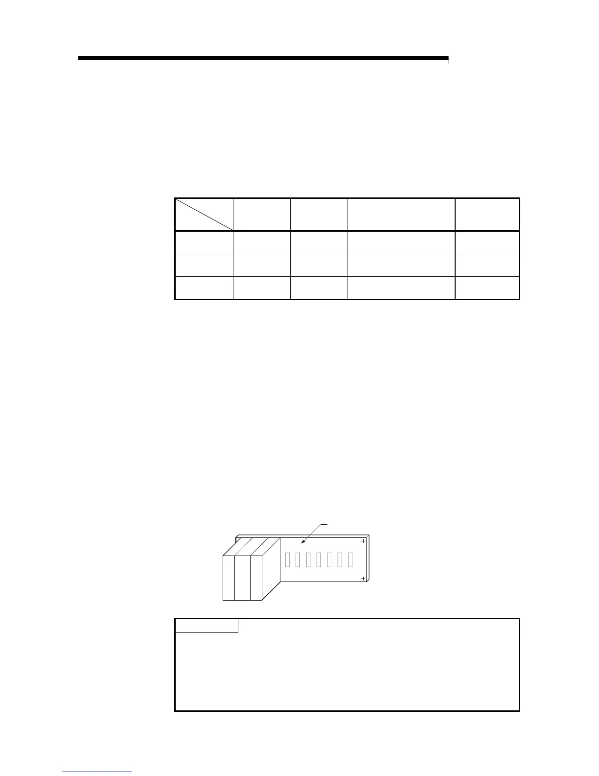
(7) AD75 mounting position
Unless particularly designated following this chapter, the sequence program for
the following conditions is shown.
•
PLC CPU module : A3UCPU
•
AD75 input/output signal : X/Y00
H
to X/Y1F
H
(When AD75 is mounted in slot 0 of the main base
unit.)
A
D
75
Main base uni
C
P
U
P
L
C
POINT
During the various processes of the special function module, the access from the
PLC CPU is processed as a priority. Thus, if the special function module's buffer
memory is frequently accessed from the PLC CPU, the PLC CPU scan time will
increase and a delay will occur in the special function module's processes.
Access the buffer memory from the PLC CPU with the FROM/TO command, etc.,
only when necessary.

 Loading...


