1 - 11
MELSEC-A
1 PRODUCT OUTLINE
V
R
L
P0
P
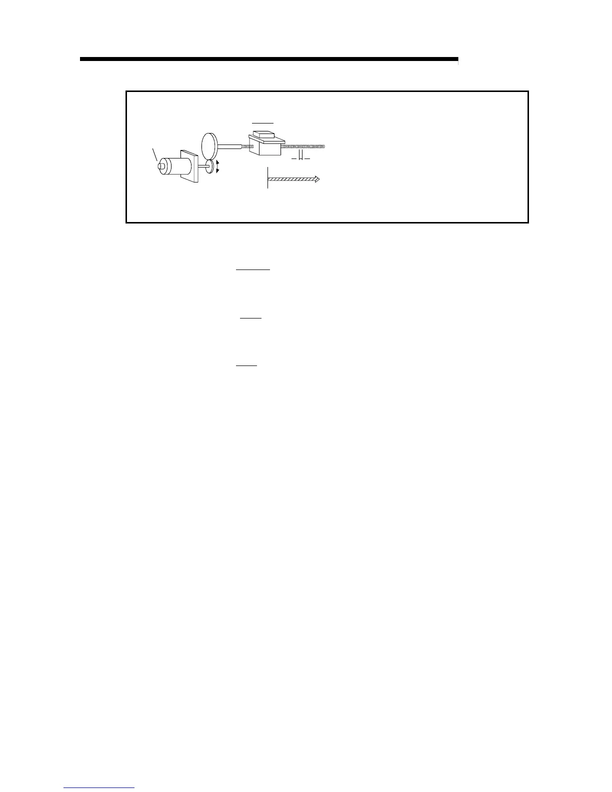
Pulse encoder
(PLG)
Workpiece
Worm gear
Table
Servomotor
A : Movement amount per pulse (mm/pulse)
Vs : Command speed (pulse/s)
n : Pulse encoder resolution (pulse/rev)
L : Worm gear lead (mm/rev)
R : Deceleration ratio
V : Movable section speed (mm/s)
N : Motor speed (r/min)
K : Position loop gain (1/s)
ε
: Deviation counter droop pulse amount
P0 : Zero point (pulse)
P : Address (pulse)
Fig.1.3 System using worm gears
(1)
Movement amount per pulse
L
A =
R
n
[mm/pulse]
(2) Command speed
V
Vs =
A
[pulse /s]
(3) Deviation counter droop pulse amount
Vs
ε
=
K
[pulse]
The movement amount per pulse is indicated with (1), and the [position/speed
command]
[
movement amount per pulse]
is the movement amount. The command
speed is calculated with (2) using the movable section speed and
movement amount per
pulse
.
The relation of the command speed and deviation counter droop pulses is shown in
(3).
As the positioning command
unit
, (mm), (inch), (degree) or (pulse) can be selected
independently for the 1 to 3 axes of the AD75.
Thus, if the data such as the movement amount per pulse, acceleration/deceleration
time, positioning speed, and positioning address are set to match the positioning
command unit, the operation will be carried out within the AD75 for the target
positioning address. The position/speed command will be output, and positioning will
be executed.

 Loading...


