12 - 59
MELSEC-A
12 CONTROL AUXILIARY FUNCTIONS
(2) Preparations
Note the contents of the following table for preparations of the absolute position
detection system.
Component Description
1) Servo amplifier
(MR-H-B (MR-H-BN),
MR-J-B, MR-J2-B,
MR-J2S-B)
•
Install the battery (MR-BAT, A6BAT) to the servo amplifier.
•
Validate the absolute position detection function of the
servo amplifier.
For other details, refer to the manual of the servo amplifier.
2) Servomotor
•
Use the servomotor with absolute position detector.
For other details, refer to the manual of the servomotor.
3) Detector cable
•
Add the connection of the battery power supply (BAT/LG
signal) to the wiring of the incremental detector cable.
For other details, refer to the manual of the cable.
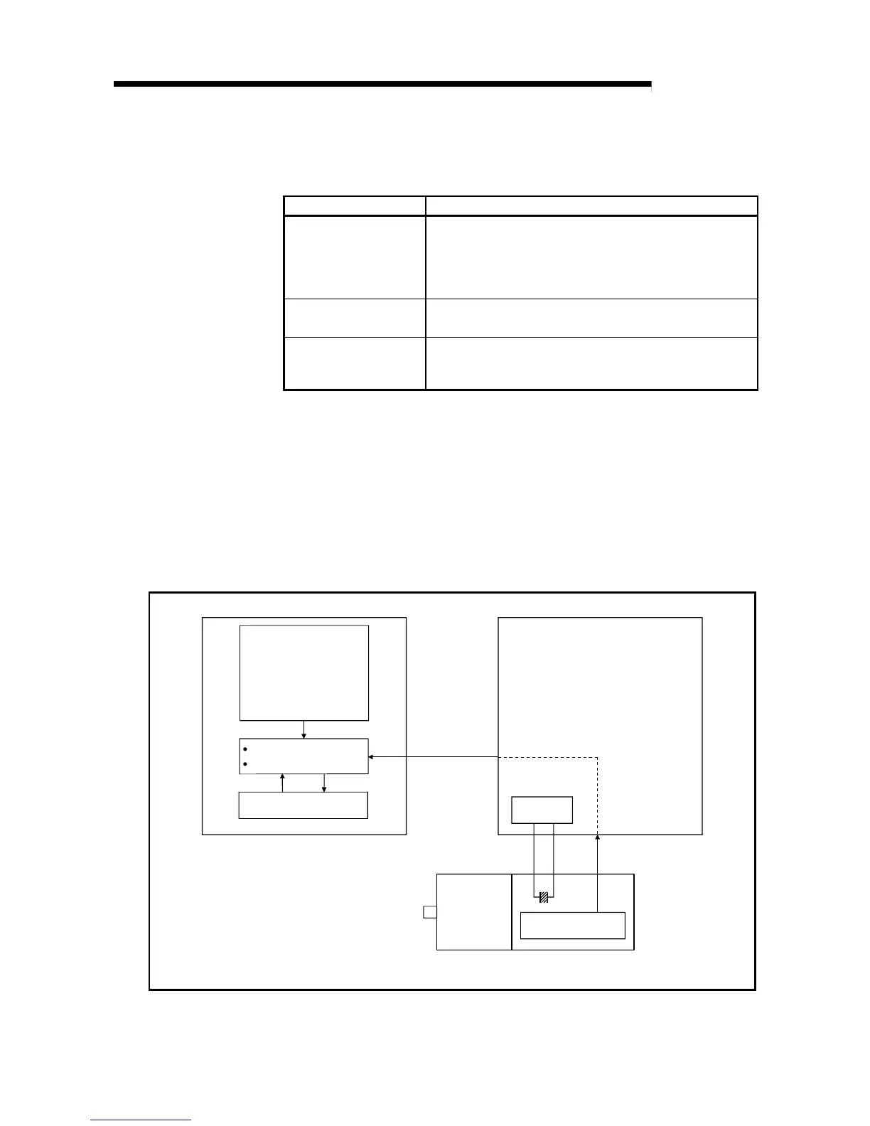
[2] Outline of absolute position detection data communication
As shown in the system block diagram in Fig. 12.32, the current absolute position is
stored by the battery fitted to the servo amplifier, and the absolute position of the zero
point is stored in the FeRAM of the AD75.
Making a zero point return once at the installation of the machine eliminates the need
for a zero point return at subsequent power-on.
After powering on the AD75 and servo amplifier, start communication between the
AD75 and servo amplifier to restore the absolute position.
AD75
Servo amplifier
Servomotor
Battery
Absolute position data
Unit setting,
No. of pulses per rotation,
Movement amount per
rotation,
Unit magnification,
Rotation direction,
Zero point address
Current feed value
Machine feed value
Absolute position of
zero point
FeRAM
Battery backup
Read
Write
(Detector)
Fig. 12.32 Outline of absolute position restoration function

 Loading...


