12 - 62
MELSEC-A
12 CONTROL AUXILIARY FUNCTIONS
Example 1.
(1) The conditions for calculating the positioning address are indicated below.
•
Movement amount per pulse: 0.1 (µm)
•
Zero point address: 0.0 (µm)
•
Number of feedback pulses = 8192 (pulse)
(2) Calculate the upper and lower limit values of the positioning address that can
be specified from the range of using the number of output pulses in Condition
1 and the expression for calculating the positioning address (Expression 1).
•
Lower limit value of positioning address (use the number of negative side
pulses in Condition 1 for calculation)
(Positioning address) = (movement amount per pulse)
(number of output
pulses) + (zero point address)
= 0.1
(
-
268435456) + 0.0
= -26843545.6 (µm)
•
Upper limit value of positioning address (use the number of positive side
pulses in Condition 1 for calculation)
(Positioning address) = (movement amount per pulse)
(number of output
pulses) + (zero point address)
= 0.1
268435455 + 0.0
= 26843545.5 (µm)
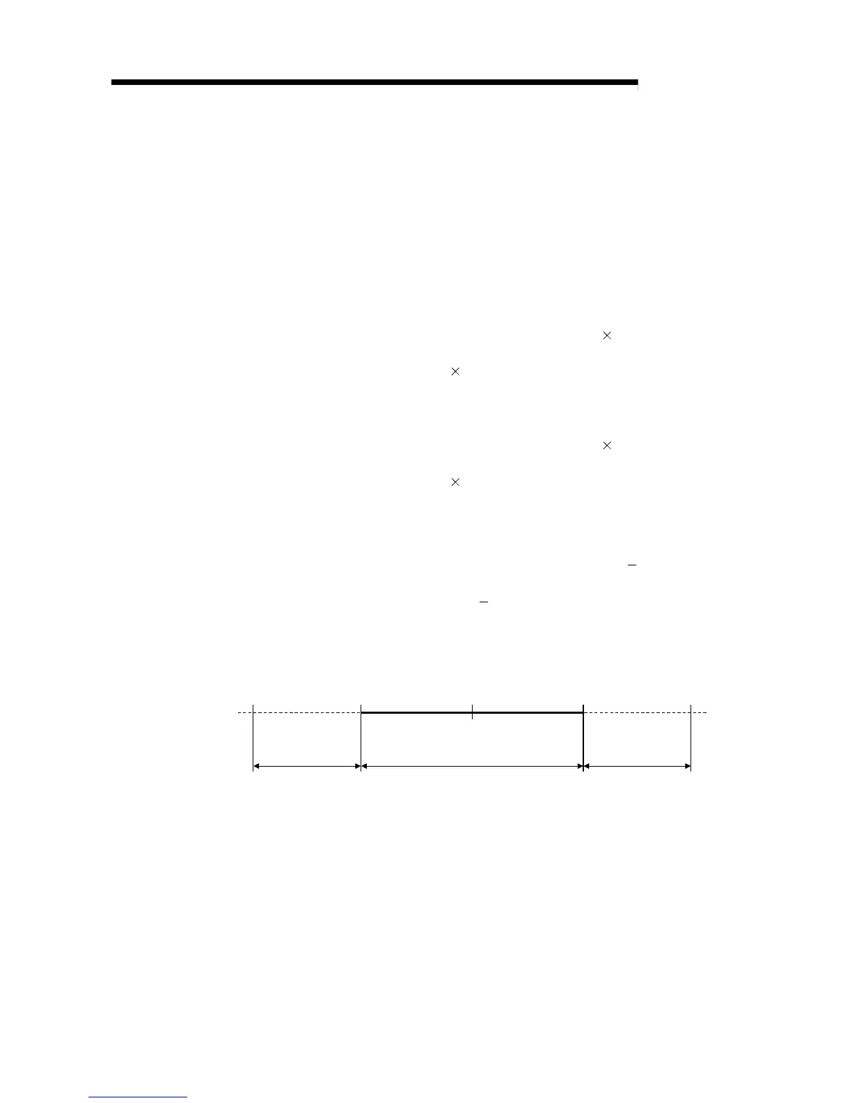
(3) The upper and lower limit values of the calculated positioning address are
within the range of Condition 2.
Hence, the positioning range calculated under Condition 1 [
26843545.6 (µm)
to 26843545.5 (µm)] can be used in the absolute position detection system.
For positioning outside the range
26843545.6 (µm) to 26843545.5 (µm), the
AD75 cannot be used in the absolute position detection system.
-26843545.6 26843545.5
Unusable range in
absolute position
detection system
Usable range in absolute position
detection system
Unusable range in
absolute position
detection system
-214748364.8 214748364.7
Unit:
µ
m
Zero point
0

 Loading...


