14 - 13
MELSEC-A
14 TROUBLESHOOTING
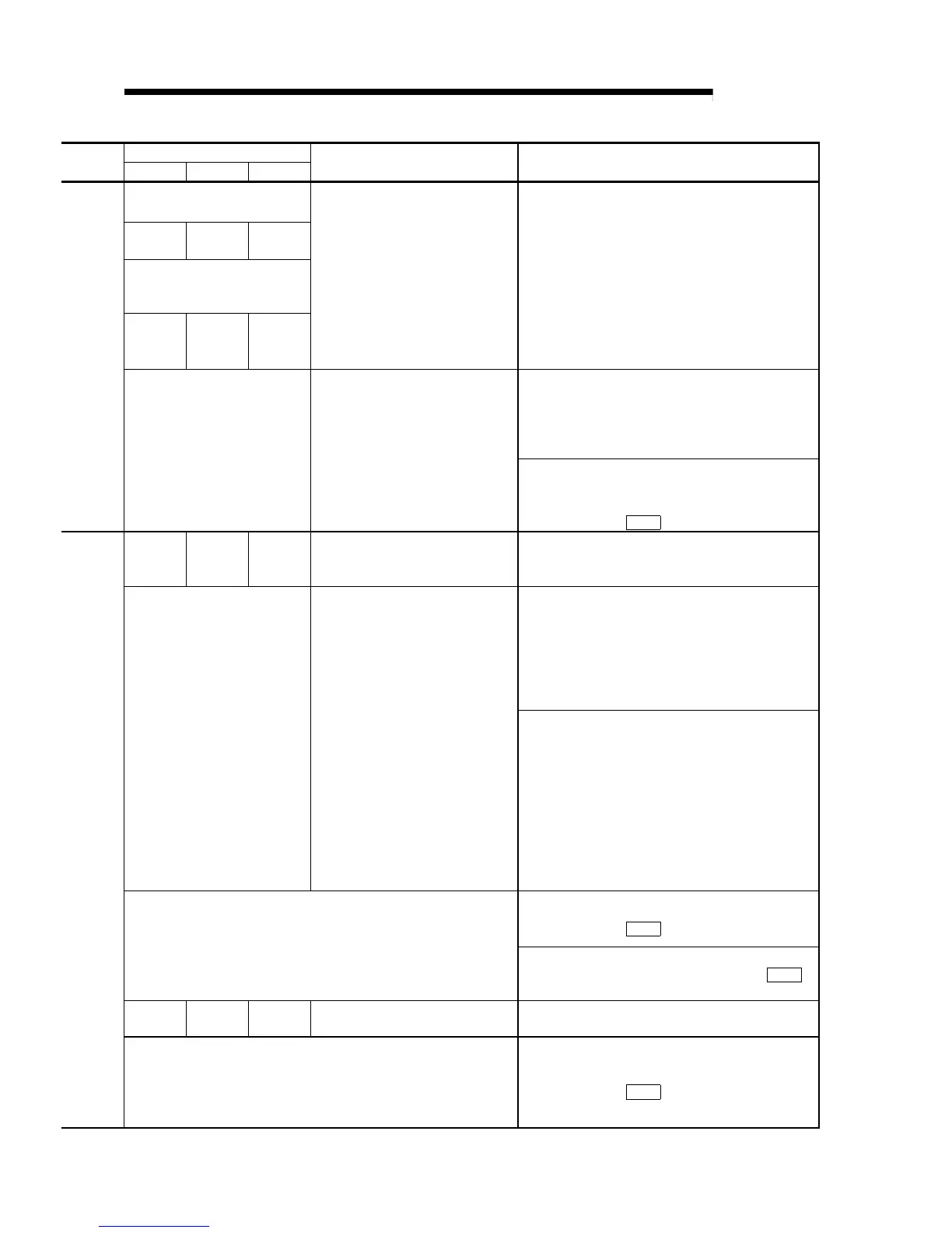
Relevant buffer memory address
Axis 1 Axis 2 Axis 3
Setting range
(Setting given in sequence program)
Remedy
Software stroke limit upper limit
value
16
17
166
167
316
317
Software stroke limit lower limit
value
18
19
168
169
318
319
<Software stroke limit upper/lower limit
value>
•
[mm] [inch] [pulse]
-2147483648 to 2147483647
•
[degree] 0 to 35999999
Change the current feed to within the range of the
software stroke limit, using manual control operation (refer
to Chapter 11).
•
Correct the positioning address to within the range of the
software stroke limit.
•
Change the current feed to within the range of the
software stroke limit, using manual control operation
(refer to Chapter 11).
Refer to section “5.3 List of
positioning data.”
<Positioning address/movement
amount>
•
[mm] [inch] [pulse]
-2147483648 to 2147483647
•
[degree] 0 to 35999999
Correct the positioning address/movement amount of the
positioning data to within the range of the software stroke
limit.
(Refer to section 5.3 Da. 5 )
1154
1155
1204
1205
1254
1255
<New current value>
[degree] 0 to 35999999
Change the new current value to within the setting range.
(Refer to section 9.2.10)
Do not designate the current value change in the
positioning data following continuous path control.
(Refer to section 9.2.10)
Refer to section “5.3 List of
positioning data.”
<Control method> 01
H
to 11
H
, 20
H
•
03
H
, 06
H
: 1 to 2 axis fixed-dimension
control
•
0D
H
, 0E
H
: Speed control
•
11
H
: Current value change
•
Speed/position changeover control:
0F
H
, 10
H
<Operation pattern> 00, 01, 11
•
01: Continuous positioning control
•
11: Continuous path control
•
Do not designate speed control, sizing feed, or
speed/position changeover control in the positioning data
following continuous path control.
•
Do not perform sizing feed, speed control, or
speed/position changeover control in the operation
pattern of continuous path control.
•
Do not perform speed control in the operation pattern of
continuous positioning control. (Refer to Chapter 9)
Correct the operation pattern.
(Refer to section 5.3 Da. 1 )
<Operation pattern>00, 01, 11
•
00: Positioning complete
•
01: Continuous positioning control
•
11: Continuous path control
Correct the control method. (Refer to section 5.3 Da. 2 )
0 150 300
<Unit setting>
0, 1, 2, 3
Correct the positioning data or the “unit setting” parameter.
(Refer to section 9.1.6)
<Control method> 01
H
to 11
H
, 20
H
•
03
H
, 06
H
: 1 to 2 axis fixed-dimension control
•
0D
H
, 0E
H
: Speed control
•
11
H
: Current value change
•
Speed/position changeover control: 0F
H
, 10
H
Correct the control method.
(Refer to section 5.3 Da. 2 )

 Loading...


