Appendix - 38
MELSEC-A
APPENDICES
FLS SIGNAL (Forward Limit Signal)
This is the input signal that notifies the user
that the limit switch (b contact configuration,
normally continuity) installed at the upper limit
of the positioning control enabled range was
activated.
The positioning operation stops when the FLS
signal turns OFF (non-continuity).
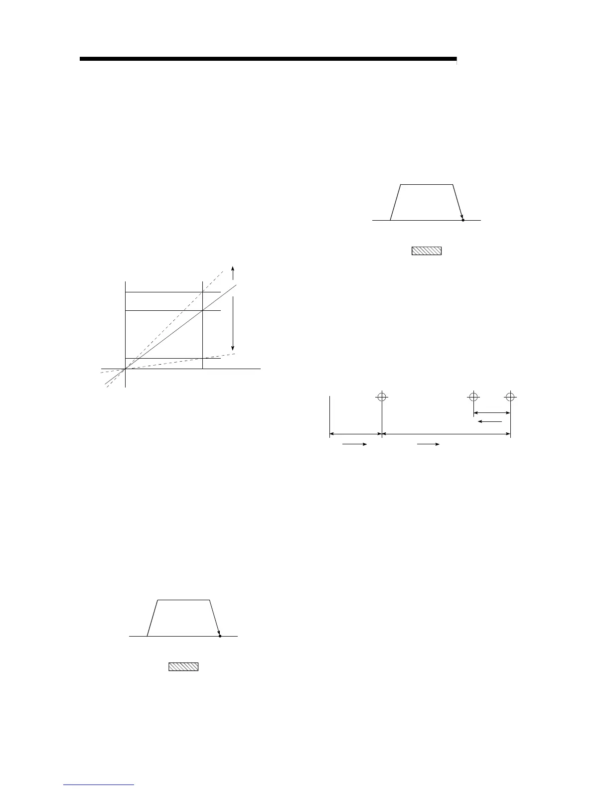
GAIN
The changing of the ratio between two values
having a proportional relation. Seen on a
graph, the changing of the incline of the
characteristics.
13
10
2
10
Raising
the gain
Output Lowering
the gain
Input
For example, when 10 is output for an input of
10, the output can be changed to 12, 5, etc.,
by changing the gain.
HIGH-SPEED MACHINE ZERO POINT
RETURN
In this zero point return method the near-point
dog is not detected. The positioning data
address is replaced with the machine zero
point address, and the positioning data is
executed to carry out high-speed positioning to
the zero point at a designated speed.
(This is not validated unless a machine zero
point return has been carried out first.)
Positioning data command speed
Zero poin
Near-point dog switch
HIGH-SPEED ZERO POINT RETURN
The axis returns to the machine zero point at
the zero point return speed without detecting
the near-point dog.
(This is not validated unless a machine zero
point return has been carried out first.)
Zero point
Near-point dog switch
Zero point return speed
INCREMENT SYSTEM
The current value is 0 in this system. Positions
are expressed by the designated direction and
distance of travel. Also called the relative
address system. This system is used in fixed-
dimension feed, etc. Compare ABSOLUTE
SYSTEM.
No.1 No.2 No.3
0
00
Stop
Left
Right Right
No. 2 is several millimeters
to the right of No. 1.

 Loading...


