2 - 27
SYSTEM CONFIGURATION2.
(a) A1SHCPU, A2SHCPU system
The following example shows the A1SHCPU system configuration, number of I/
O points, I/O assignment of a stand-alone system.
System Configuration
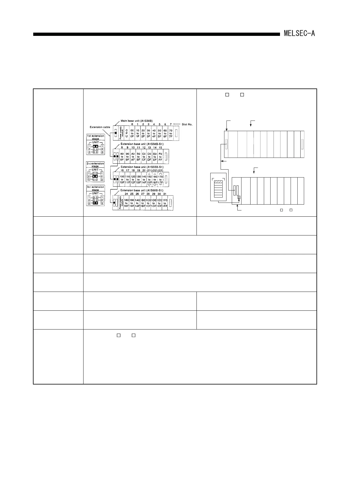
[When the AnS extension base is used]
The following shows an example that the 16-point
module is installed to each slot.
[When the A N, A A extension base is used]
The following shows an example that the 16-point
module is installed to each slot.
Maximum number of
extension stages
3rd extension stage 1st extension stage
Maximum number of
I/O modules
16 modules
Maximum number of
I/O points
A1SHCPU: 256 points, A2SHCPU: 512 points
Main base unit model
name
A1S32B, A1S33B, A1S35B, A1S38B
Extension base unit
model name
A1S65B(S1), A1S68B(S1), A1S52B(S1),
A1S55B(S1), A1S58B(S1)
A62B, A65B, A68B, A52B, A55B, A58B
Extension cable
model name
A1SC03B, A1SC07B, A1SC12B, A1SC30B,
A1SC01B (right-side installation), A1SC60B
A1SC05NB, A1SC07NB, A1SC30NB, A1SC50NB
Precautions
(1) Only one A N, A A extension base can be used.(The second extension module cannot be used.)
(2) When the extension base A1S52B(S1), A1S55B(S1), A58B(S1) or A52B, A55B, A58B are used, the 5VDC
power is supplied from the power supply module of the main base unit. Before use, refer to Section 6.1.3
and examine if it can be used.
(3) Limit the length of extension cable to 6m (236inch) or shorter.
(4) When using the extension cable, do not install it with the main circuit cables, which has high voltage, large
current, or install them close together.
0234
5
617
8 9 10 11 12 13
14 15
80 90
9F
A0
AF
B0
BF
C0
CF
D0
DF
E0
EF
F0
FF
8F
00
0F
10
1F
20
2F
30
3F
40
4F
50
5F
60
6F
70
7F
UNIT
1
2
3
4
5
6
7
1
2
3
4
5
6
7
Main base
unit
(A1S38B)
Slot No.
Slot No.
Extension cable
1st extension
stage
Power supply
module
Power supply
module
CPU module
to
toto
to to to to to to to to
to to to to to
Extension base unit (for A N, A A)

 Loading...