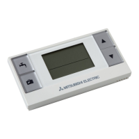
<EHPT20X-*M*HB/*M*B (except EHPT20X-VM2HB)> (Packaged model system)
Number Component
1 Automatic air vent
2 Pressure relief valve
3 Expansion vessel
4 Main controller
5 Control and electrical box
7 Immersion heater (Only for EHPT20X-*M*HB)
8 DHW tank
9 3-way valve
10 Water circulation pump
11 Manual air vent
12 Booster heater
13 Drain cock (Booster heater)
14 Strainer valve
15 Flow switch
16 Drain cock (Primary circuit)
17 Drain cock (DHW tank)
19 Manometer
A DHW outlet
B Cold water inlet
E Inlet from space heating
F Outlet to space heating
G Inlet from heat pump
H Outlet to heat pump
<Figure 3.4>
<Table 3.5>
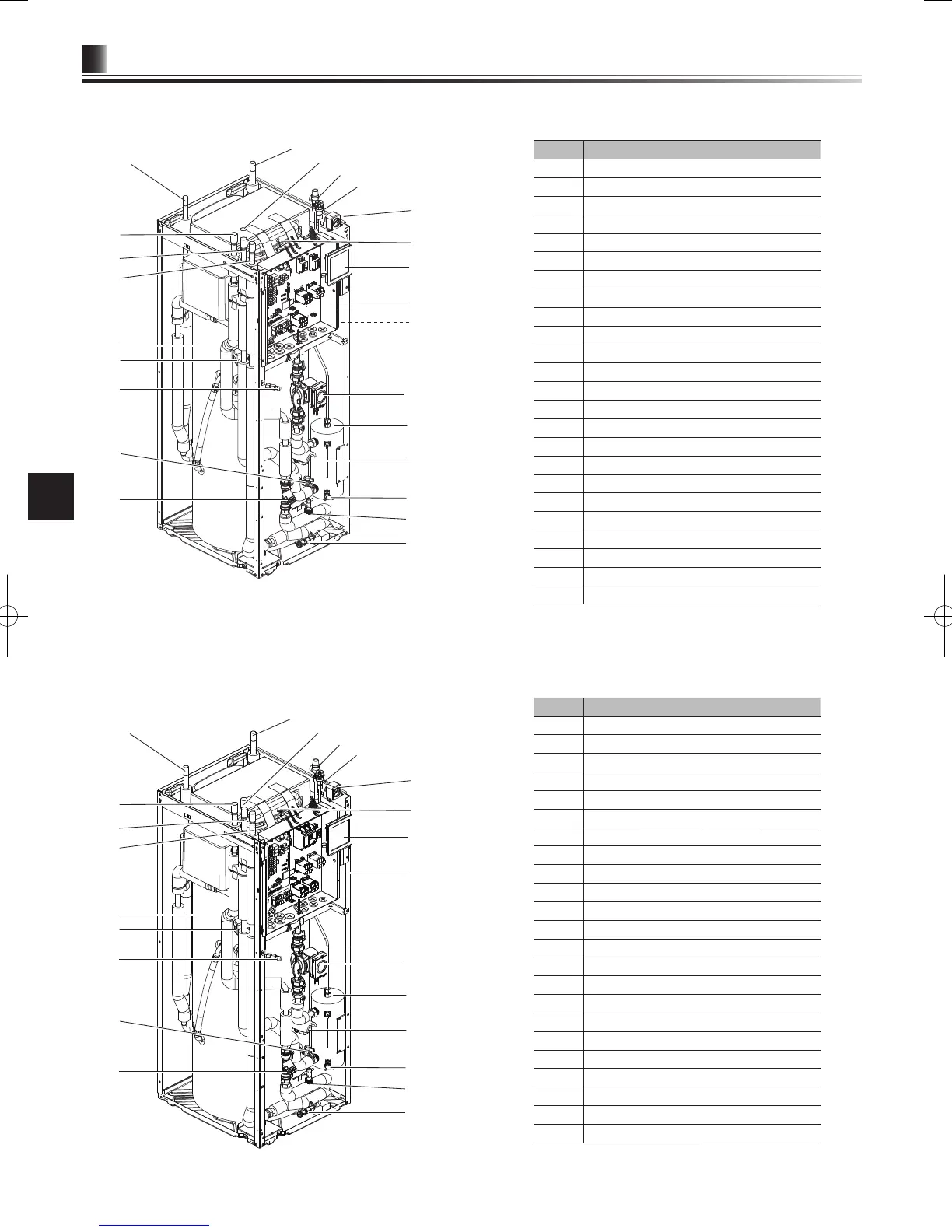
<EHPT20X-VM2HB> (UK Packaged model system)
Number Component
1 Automatic air vent
2 Pressure relief valve
3 Expansion vessel
4 Main controller
5 Control and electrical box
6 Temperature and pressure relief valve (not visible)
7 Immersion heater
8 DHW tank
9 3-way valve
10 Water circulation pump
11 Manual air vent
12 Booster heater
13 Drain cock (Booster heater)
14 Strainer valve
15 Flow switch
16 Drain cock (Primary circuit)
17 Drain cock (DHW tank)
19 Manometer
A DHW outlet
B Cold water inlet
E Inlet from space heating
F Outlet to space heating
G Inlet from heat pump
H Outlet to heat pump
<Figure 3.3>
<Table 3.4>

 Loading...