EasyManua.ls Logo

Mitsubishi FR-E540-7.5K-NA - Structure

Mitsubishi FR-E540-7.5K-NA
224 pages
To Next Page IconTo Next Page
To Previous Page IconTo Previous Page
Loading...
OUTLINE
4
1.3 Structure
1.3 Structure
1.3.1 Appearance and structure
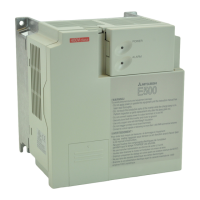
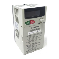
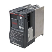
(1) Front view
POWER lamp
(yellow)
Accessory cover
ALARM lamp (red)
Rating plate
Front cover
Capacity plate
Wiring port cover
for option
(
100V class, 200V class
)
(400V class)
(2) Without accessory cover and front cover
Control circuit
terminal block
Main circuit
terminal block
Wirin
g
cover
Inboard option
mounting position
PU conector*
POWER lamp (yellow)
ALARM lamp (red)
Connector for connection
of inboard option
(400V class only)
(400V class)
(
100V class, 200V class
)
Control logic changing
connector
(400V class only)
*Use the PU connector for the FR-PA02
-02
or FR-PU04 option and RS-485
communication.
1

Table of Contents

Related product manuals