7.
SElTlNG
PARAMETERS
BEFORE
STARTUP
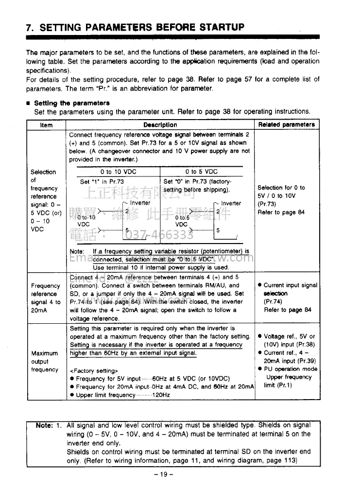
The major parameters to be set, and the functions
of
these
parameters, are explained
in
the fol-
lowing table. Set the parameters according
to
the application requirements (load and operation
specifications).
For details
of
the setting procedure, refer to page
38.
Refer
to
page
57
lor a complete list of
parameters. The term "Pr." is an abbreviation for parameter.
Setting
the
parameters
Set the parameters using the parameter unit. Reler
lo
page
38
lor operating instructions.
Itern
Selection
of
frequency
reference
slgnal:
0
-
5
VDC (or)
0-
10
VDC
Frequency
reference
signal 4 to
20mA
Maximum
output
frequency
Description
:onnecl frequency refereme vMaga
signal
Ween terminals 2
+)
and
5
(common).
Set
Pr.73 for a
5
or 1OV signal as Shown
!elow. (A changeover connector and 10
V
power supply are not
rrovided in
the
inverter.)
__~
0
to
10
VDC
Set '1" in Pr.73
Inverter
010
10
0 to
5
VDC
Set
r)"
in Pr.73 Ifactow
setting before shipping).
..
VDC
Jote:
If
a frequency setting variable resistor (potentiometer) is
connected, selection must
be
'0
to
5
VDC".
Use terminal
10
U
internal power
supply
is
used.
:onnect 4
-
20mA reference between terminals
4
(+)
and
5
common). Connect a switch between terminals RWAU, and
3D, or a jumper
if
only the
4
-
20mA signal will be used. Set
'r.74 to
1
(see
page
84).
With the switch closed, the inverter
Hill
follow the
4
-
20mA slgnal: open the switch to follow a
loltaae reference.
jetting this parameter is required only when
the
inverter is
merated at a maximum freauencv other than the factory setting.
..
jetting is necessary
if
the inverter
is
operated at a frequency
ligher than
6OHz
by
an external input signal.
<Factory setting>
D
Frequency
for
5V Inpat
...
.60Hz
at
5
VDC (Or 1OVDC)
D
Frequency for 20mA input.
OHz
at 4mA DC, and
BOHz
at 20mP
D
Umer limil freauencv
'
120Hz
Related
prarneters
Selection
for
0
to
5V
/
0
to 1OV
(Pr.73)
Refer to page
84
Current input signa
selection
(Pr.74)
Refer to
page
84
Voltage ref., 5V or
(1OV) input (Pr.38)
0
Current ref.,
4
-
20mA input (Pr.39)
PU operatibn mode
Upper
frequency
limit (Pr.l)
Note:
1.
All
signal
arid
low
level control wiring must be shielded type. Shields on signal
wiring
(0
-
5V,
0
-
IOV.
and
4
-
20mA) must be terminated at termiml
5
on the
inverter end only.
Shields on control wiring must
be
terminated at terminal
SD
on the inverter end
only. (Refer
to
wiring information, page
11,
and wiring diagram, page
113)
-
19-
 Loading...