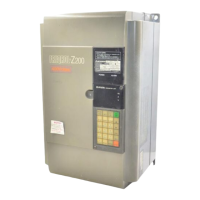
Do you have a question about the Mitsubishi FREQROL FR-A024-1.5K and is the answer not in the manual?
| Brand | Mitsubishi |
|---|---|
| Model | FREQROL FR-A024-1.5K |
| Category | Inverter |
| Language | English |
Precautions to prevent electric shock during inverter operation and maintenance.
Precautions to prevent fire hazards related to inverter installation and use.
Precautions to prevent personal injury from inverter operation and maintenance.
Warning against connecting power supply to output terminals U, V, W.
Warning against using magnetic contactors for frequent start/stop of the motor.
Safety warning about high voltage circuits inside the inverter.
Warning against connecting specific components to the inverter output.
Importance and method of grounding the inverter and motor for safety.
Information on using the parameter copy unit for parameter data transfer.
Considerations for installing the inverter, including location and environmental conditions.
Connecting input power, output, and control signal lines to the terminal block.
Describes the three operation modes: External, PU, and Combination.
Guidelines for upright installation to ensure proper heat radiation.
Importance of maintaining ambient temperature within specified limits for inverter service life.
Important cautions to consider when wiring the inverter to avoid errors or damage.
Checks for commercial power supply selector circuits and behavior during power interruption.
Instructions for connecting the power supply and motor to the inverter's terminal block.
Diagram and notes for connecting various control signals to the inverter.
Guidelines and cautions for operating the inverter using a single-phase power supply.
Step-by-step wiring procedures for standard and fully enclosed specifications.
Wiring procedures for standard specifications (FR-A024/FR-A044).
Guidelines for selecting wire size and managing wiring distance to prevent voltage drop and current limit issues.
Wiring procedures for fully enclosed specifications (FR-A024-C/FR-A044-C).
Warnings related to inverter operation using the parameter unit.
Conditions and parameters that can be written or not written under different operation modes.
Conditions under which operation mode cannot be switched.
Explains external, PU, and combination operation modes.
Covers reading, updating, and clearing parameters.
Describes checking operation status and alarm contents.
Classification of operation modes: External, PU, and Combined.
How to switch between external, PU, and combination operation modes.
Detailed procedure for operating the inverter using external signals.
Procedure for ordinary operation using the parameter unit.
Procedure for performing jog operation using the parameter unit.
How to combine external signals and parameter unit for operation.
Procedure for using external frequency and parameter unit for start/stop.
Using external start/speed signals with parameter unit settings.
How to switch between operation modes while the inverter is running.
How the edit enable signal mode enables/disables parameter writing.
How to change operation mode using external signals via terminal RH.
Step-by-step procedure for reading and writing parameter values using the parameter unit.
Procedure for clearing parameters to factory settings.
Procedure for clearing all parameters to factory default.
How to change monitor information using monitor keys.
Lists common error codes, their probable causes, and corrective actions.
Procedure for checking the contents of stored errors.
Procedure for clearing the error log.
How to use the parameter unit disconnection detection function and its effects.
Cautions regarding the parameter unit disconnection detection function.
Step-by-step procedure for calibrating the frequency meter.
Explains how to adjust bias and gain for voltage/current frequency setting signals.
Conditions that must be met for effective use of magnetic flux vector control.
Lists parameters related to magnetic flux vector control.
Procedure for setting parameter 98 to invalidate current limits for long wiring distances.
Procedures for setting parameters 77 and 98 for flux vector control.
How to set motor capacity and applicable motor for magnetic flux vector control.
Procedures for setting parameters when wiring distance is long.
Lists parameters for alarm clear and inverter reset.
Parameters for setting torque boost, upper and lower limit frequency.
Parameter for setting the base frequency and its voltage.
Parameters for setting multiple-speed selections.
Parameters for acceleration/deceleration time and electronic thermal relay.
Parameters for DC injection braking and starting frequency.
Parameters for stall prevention function operation level.
Parameter for selecting acceleration/deceleration pattern.
Parameters for setting regenerative brake duty ratio.
Parameters for serial communication functions.
Parameter for setting the speed display unit.
Parameter for frequency at 5V (10V) input.
Parameter for frequency at 20mA input.
Identifies parts that may deteriorate and require replacement.
Guidelines for measuring voltage, current, and power in the main circuit.
How the parameter unit displays fault codes and troubleshooting steps.
Common troubles, their check points, and potential causes.
Lists inverter protection functions, their descriptions, and display codes.
General measures to prevent noise interference with the inverter and peripheral devices.
Guidelines for power harmonic suppression.
Explanation of leakage current and measures to take.
Explains the function of each terminal on the inverter.
How to select the rated sensitivity current for earth leakage circuit breakers.


