..
.
..
. ._
~.-.
.
-.
.
22,
PARAMETERS
Pr.40
-
Or.41
Senlng
me
allocation
~f
output
terminair
Pr.a...RFM
0
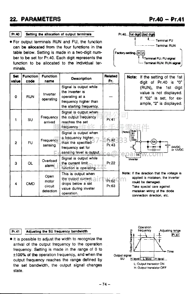
For output terminals
RUN
and
FU,
the function
1.
'-
-~
TermlnaiN
can
be
akcated from the four functions
in
the
table below. Setting is made
in
a twodigit nun
(~-.~tfho.@@
-l
~
Terminal
RUN
ber
to
be
set for Pr.40. Each digit represents the
function
to
be allocated
to
the
individual ter-
minals.
Sal
Fumllor
MIW
code
0
RUN
1
su
2
FU
3
OL
4
OMD
Funcllon
name
Inverter
operating
Frequency
arrived
Frequency
sensing
Overload
alann
Open
motor
detection
circuit
Signal is output while
the inverter
IS
operating at a
frequency higher than
Signal is output when
the output frequency
reaches the
set
freauencv.
Pr.41
Signal
is
output when
a frequency higher
than the specified
frequency
set
for
sensing level
is
output.
Signal
is
output while
the
current
limit
function is operating.
Pr.22
This
is
output when
the output current
drops below a set
value during lnveter
operation.
pr,43
Pr.42
Pr.62
Pr.63
Adju8ting
h
SU
froqu~~cy
bandrvldth
It
is possible
to
adjust the width to recognize the
arrival
of
the output frequency
to
the operatin
frequency.
Setting
is made in the range of
0
to
flw%
of
the
operation frequency, and when the
wputrig~
oulput frequency reaches the range defined by
SU
H
I
vel
HI
v
I..
the set bandwidth, the output signal changes
L:
Oulpn
lransslor
ON
state.
Operallon
H:
Output
lraruislor
OFF
J
Note:
If the setting of the
lsl
digit of Pr.40 is
"0"
(RUN),
the 1st digit
value is not displayed.
If "02"
is set, for ex-
ample,
'2"
is displayed.
Nota:
If
bre chredion
bret
the
voltage
IS
coold
be
damam.
applied
is
mistaken,
me
Inverter
Take
special
care
against
mstakm
wiring
d
\he
dode
mnnedh
chreotion,
etc.
-
74
-
 Loading...