*,
.
..
,.-
.-.
_.._.
-.
..
,I
.
22.
PARAMETERS
Pr.59
.I
..
Notes:
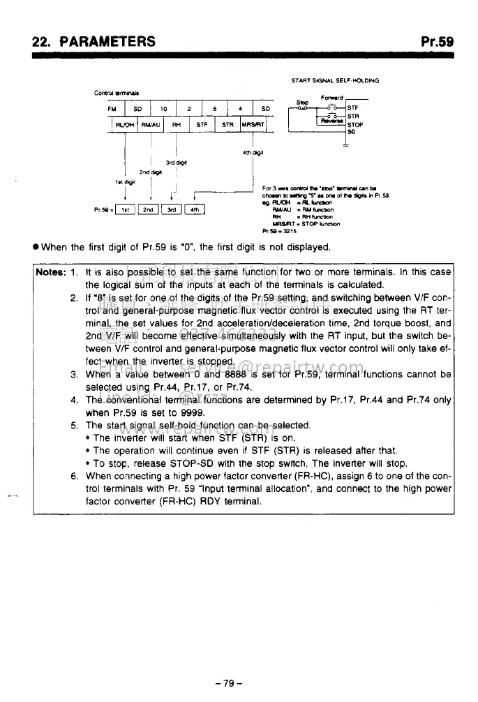
1.
It
IS
also possible to set the same function for two or more terminals. In this case
the logical sum of the inputs at each of the terminals is calculated.
2. If
'8'
is set for one of the digits of the Pr.59 setting, and switching between
VIF
con-
trol and general-purpose magnetic flux vector control is executed using the RT ter-
minal, the set values for 2nd
acceleration/deceleration
tme, 2nd torque
boost,
and
2nd VIF will become effective simultaneously with the RT input, but the switch be-
tween
V/F
control and general-purpose magnetic flux vector control will only take ef-
fect when the inverter is stopped.
3.
When a value between
0
and
8888
is set for Pr.59, terminal functions cannot be
selected using Pr.44, Pr.17, or Pr.74.
4.
The conventional terminal functions are determined by Pr.17, Pr.44 and Pr.74 only
when Pr.59 is set to 9999.
5. The start signal self-hold function can be selected.
The inverter WIII start when STF (STR)
is
on.
The operation will continue even
if
STF (STR) is released after that.
To stop, release STOP-SD with the stop switch. The inverter will stop.
6.
When connecting a high power factor converter (FR-HC), assign
6
to one of the con-
trol terminals with Pr. 59 'Input terminal allocation", and connect to the high power
factor converter
(FR-HC) RDY
terminal.
-79
-
 Loading...