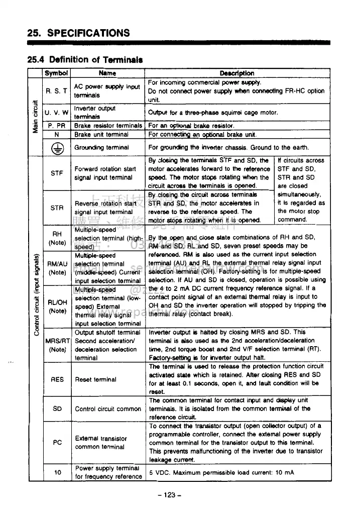
25.
SPECIFICATIONS
25.4
Definition
of
Terminals
STR
RH
(Note)
-
RWAU
(Note)
-
RUOH
(Note)
-
ARS/RT
(Note)
RES
SD
-
PC
10
Name
9C power
supply
input
terminals
Inverter
outprt
terminals
Braka
resistor terminals
Brake unit terminal
Groudicg termlnal
Fomerd rotation start
signal input terminal
Reverse rotation start
signal input terminal
Mukiile-speed
selection terminal (high.
selection terminal
(middle-spwd)
Current
input
selection
terminal
Multple-speed
selection terminal (low-
speed)
External
thermal relay signal
input
sel&
terminal
Output
shutdf terminal
Second acceleration/
deceleration selection
terminal
Reset terminal
Control circuit commm
External transistor
common terminal
Power supply tenninal
for frequency reference
De.alptlon
For incoming commercial
power
WKQIY.
DO
not conA power
supply
*rhen mg
FR-HC
option
..
.
ovtpa
for
a
three-phase
squirrel
cage
motor.
For
M
opti
brake
resislor
For connectinp
an
OptiMal
brake unil
For grounding
he
lnwwter chassis. Ground to the earth.
By
ck&g
the
terminals STF and SD.
the
If
circuits across
motor accelerates forward to
tha
rdaence
the motor stop
reverse
to
the
reference
speed.
The
it
is regarded
as
STR
and
SD,
the
motor
accelerates
in
simultrnusb,
By
dosing
the
drcuit
mobs
terminab
are closed
circuit aCrw
the
tminals
is
opened.
STR and
SD
speed.
The
motor
s.tc+s
rotating
when
the
STF and SD.
mmrnand.
motor
stops
rotatkg when
it
is
opened.
By
the
open
and
close
state comblnations of
RH
and
SD,
RM
and
SD.
RL
and
SD, seven preset
speeds
may
be
referenced.
RM
is
also
used
as
the
current input selection
terminal
(AU)
and
RL
the external
thermal
relay signal input
selection
terminal
(OH).
Factorpsetting
is
for muttiple-speed
se!e3ii.
If
AU
and SD
IS
closed, operation is possible wing
the
4
to 2
m4
DC current frequency reference signal. If a
contaCt point
dgnal
of an external
thermal
relay is input to
OH
and SD the inverter operation
will
stopped by tnpping
the
thermal relay (contact break).
Invecter
oulput
is
halted by closing
MRS
and
SD.
This
terminal
is
elso
used
as
the
2nd acceleratioddecelatim
ti,
2nd torque
boost
and 2nd
VF
selection
terminal (RT).
Fsctory-wtthg
b
for hverter output halt.
The terminal
is
used
to release
the
protection function circuit
activated
state
which
is
retained. Mer
cbsing
RES
and SD
for
at
least
0.1
seconds,
open
I&
and
fault
condaion
will
be
mt.
The
common
tenninal for contau input and my unl
terminals.
It
is
isolated from
the
commcn
terminal
of
the
To
conned
tha
t-tor
output
(om
cdledor wtput) of a
reference circuit
programmable controller, connect the axtemal power supp~y
common terminal for
the
trarsMor
output
to
thii
terminal.
This prevents manunctioning
of
the
inverter
due
to transistor
leakage cummt.
5
VDC. Maximum
permissible
load
current:
10
mA
-
123
-
 Loading...