\
6.
WIRING
6.1
Precautions
When wiring, consider the following items to avoid erroneous operation, damage or incorrect
usage to the inverter.
Cautions on Wiring
(1)
Do
not connect the power supply wires to the output terminals
(U,
V,
W)
01
the inverter.
If
they are connected to these terminals,
it
will damage the inverter.
(2)
Terminals P and
PR
are used for connection
01
the optional brake resistor (refer to
page
131).
Never short circuit or connect anything other than the brake resistor across
these terminals.
(3)
Use sleeved
solderless
terminals for the connection
of
the power supply and the motor.
(4)
Common terminals
SD,
5,
and
SE
in
the terminal block for the control circuit are not
at the same potential.
Do
not connect or ground these terminals.
(5)
Use only shielded or twisted caMes to connect the control circuits. These wires must
be
routed as far as possible from the main power and AC relay logic circuits.
(6)
During wiring, close the
slots
on
the top of the inverter with a cover
so
that cut pieces
of
wire
will
not
enter
the
inverter.
(7)
If
modilkation
of
the
wiring
OT
other work becomes necessary aiter operating the in-
verter, do not touch the wire or terminals until power is disconnect and the POWER
CHARGE indicating lamp is extinguished for at least
two
minutes.
(8)
Any pekon who is involved in the wiring
of
this equipment should
be
fully competent
to carry out the work.
-
Wire
Size
and
Wiring
Distance
(1)
If
the motor is installed a long distance from the inverter, available motor torque will
be reduced due to voltage drop in the motor cable, especially when the motor is
operating at low frequencies. Select the wire size
so
that voltage drop is
less
than
2%.
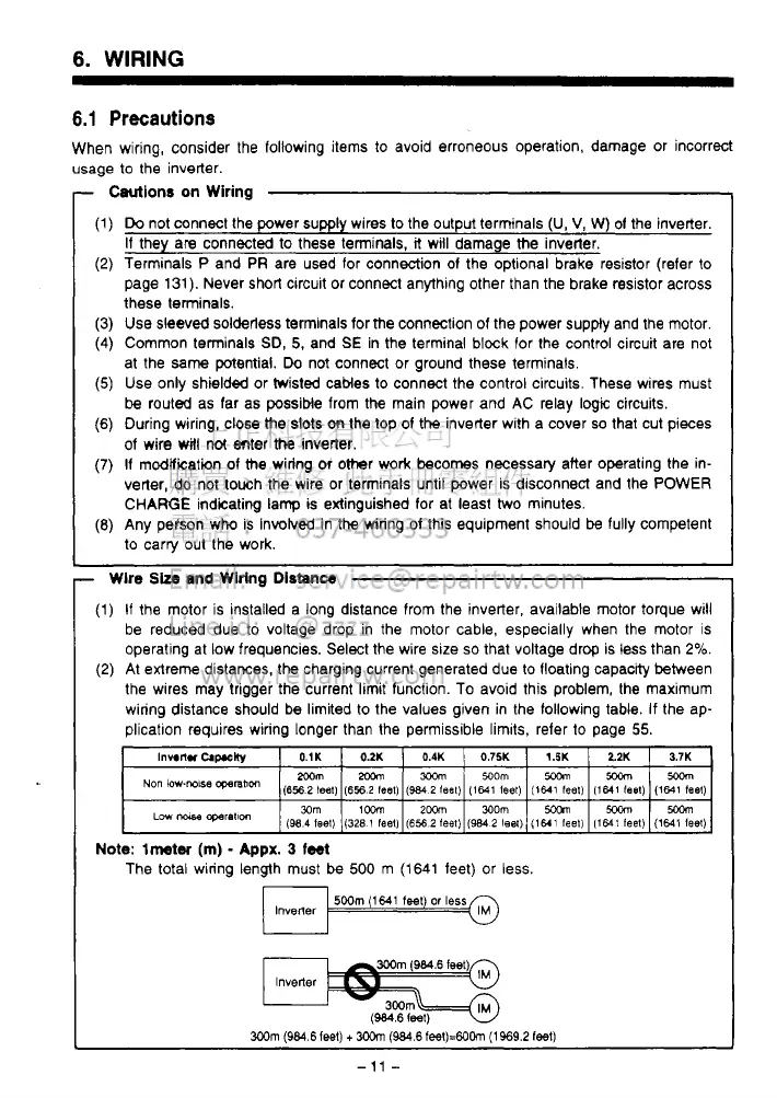
(2)
At extreme distances. the charging current generated due to floating capacity between
the wires may trigger the current limit function. To avoid this problem, the maximum
wiring distance should be limited
to
the values given in the following table. If the ap-
plication
requires wiring longer than the permissible lirnlts, refer to page
55.
Note:
lmtw
(m)
-
Appx.
3
feet
The total wiring length must
be
500
m
(1641
feet) or
less.
lnvener
500m
(1MI
feet)
or
less
IM
lnvelter
3Wm
(984.6 feet)
+
3oom
(984.6
feet)=6OCin
(1969.2
1881)
-
11
-
 Loading...