Do you have a question about the Mitsubishi FX1S-10MR-ES/UL and is the answer not in the manual?
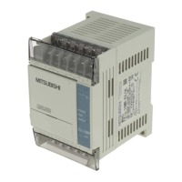
| Type | Programmable Logic Controller |
|---|---|
| Series | FX1S |
| Input Points | 6 |
| Output Points | 4 |
| Output Type | Relay |
| Power Supply Voltage | 100-240 VAC |
| Mounting Type | DIN Rail |
| Memory Capacity | 2000 Steps |
| Input Type | Digital |
| Program Memory | EEPROM |
| Certification | UL, CE |
| Dimensions (W x H x D) | 90 x 90 x 60 mm |
Explains how to interpret the product model nomenclature for FX1s.
Details differences between world and Japanese specifications for FX1s.
Describes the format and meaning of product serial numbers.
Illustrates system configuration and component connections.
Lists and describes optional units and accessories for the FX1s PLC.
Outlines restrictions on expanding the PLC system's capabilities.
Explains data retention and capacitor backup functionality.
Shows terminal layouts for AC power, relay output units.
Shows terminal layouts for DC power, relay output units.
Shows terminal layouts for DC power, transistor output units.
Details the physical features and components of the FX1s PLC.
Explains methods for controlling the PLC's operating mode.
Lists environmental and performance specifications for the PLC.
Provides guidelines and cautions for mounting the PLC unit.
Describes the procedure for mounting the unit on a DIN rail.
Details best practices for terminating wires at screw terminals.
Guides on installing additional modules and boards.
Explains the installation process for special function boards.
Details the installation procedure for the FX1N-5DM display module.
Offers best practices for safe and effective wiring.
Highlights crucial safety precautions for wiring the PLC.
Explains AC power connection requirements and safety.
Provides detailed input power specifications for different models.
Illustrates example wiring diagrams for AC and DC power input.
Specifies requirements and recommendations for grounding the unit.
Details electrical specifications for 24V DC inputs.
Provides diagrams for connecting input signals.
Shows typical wiring configurations for input signals.
Illustrates input circuit diagrams for source/sink configurations.
Explains how to connect diodes and inputs in series.
Details using resistors for parallel input connections.
Demonstrates typical wiring for relay output operations.
Presents data on the life cycle performance of relay outputs.
Explains factors affecting output response times.
Shows typical wiring configurations for transistor outputs.
Provides guidance on connecting loads safely to outputs.
Outlines initial checks before operating the PLC.
Describes troubleshooting steps for CPU error indication.
Lists frequently encountered error conditions and their causes.
Provides general maintenance procedures for the PLC.
Explains internal flags used for monitoring operation and errors.
Details registers used for monitoring PLC status and version.
Lists registers containing specific error codes and information.
Provides a reference for specific error codes and their meanings.
A comprehensive list of PLC programming instructions, sorted numerically.
Lists and describes the PLC's internal memory devices and capacities.


