HEAD OFFICE : MITSUBISHI DENKI BLDG MARUNOUTI TOKYO 100-8310
HIMEJI WORKS : 840, CHIYODA CHO, HIMEJI, JAPAN
2. Installation and wiring
INSTALLATION PRECAUTIONS
• Use the module in the environment described in the USER’S MANUAL General Specification.
Do not use the PLC in a place with dust, soot, conductive dust, corrosive gas or combustible
gas, place exposed to high temperature, condensation, wind or rain or place with vibration or
impact.
Using the module outside the range of the general specification may result in electrical shock,
fire, malfunctions, or may damage the PLC.
• When drilling screw holes or performing wiring, make sure that cutting chips, wire chips or
other foreign matter does not enter the ventilation window of the module.
Such matter may cause fire, failure or malfunction.
• When the installation work is completed, remove the dust protection sheet from the ventilation
window of the PLC.
If the sheet remains attached, it may cause fire, failure or malfunction.
• Securely connect extension cables to specified connectors.
Poor contact may cause malfunction.
WIRING PRECAUTIONS
• Before beginning any installation or wiring work, make sure all phases of the power supply
have been shut down from the outside.
Incomplete shutdown of the power supply phases may cause electrical shock or damage in the
module.
• Following an installation or wiring work, when turning on the power supply and operating the
PLC, make sure that the terminal cover provided as an accessory has been attached to the
module.
Non-attachment of the cover may cause electrical shock.
• For the CC-Link system, use dedicated cables specified by the manufacturer.
The performance of the CC-Link system cannot be guaranteed with any cable other than
dedicated ones specified by the manufacturer.
For the maximum total extension length and the cable length between stations, observe the
specification described in USER’S MANUAL.
With wiring outside the specification range, normal data transfer cannot be guaranteed.
• Make sure to fix communication cables and power cables connected to the module by placing
them in the duct or clamping them.
Cables not placed in duct or not clamped may hang or shift, allowing them to be accidentally
pulled, which may result in malfunction or damage to the module and the cables.
• When disconnecting a communication/power cable connected to the module, do not hold the
cable area.
For a cable with connector, hold the connector attached to the module.
For a cable connected to a terminal block, loosen screws of the terminal block, then disconnect
the cable.
If a cable is pulled while it is connected to a module, the module may malfunction or the
module and the cable may be damaged.
WIRING PRECAUTIONS
• Grounding resistor 100
Ω
or less with a wire of 2 mm
2
or more to the grounding terminal in the
PLC main units. However, never perform common grounding with a high voltage system.
• Do not bundle control cables and communication cables with the main circuit and power
cables. Keep control cables and communication cables at least 100 mm away from the main
circuit and power cables.
Otherwise, electric noise may cause a malfunction.
2.1 Installation
Install the FX
2N
-16CCL-M on the right side of an FX
1N
/FX
2N
/FX
2NC
Series main unit, extension unit or
another extension block. (For the FX
2NC
Series, the FX
2NC
-CNV-IF is required.)
The FX
2N
-16CCL-M can be installed using a DIN rail (DIN 46277, width: 35 mm (1.38 in.)) or directly with
M4 (0.16 in.) screws.
In the case of direct installation, provide space of 1 to 2 mm (0.04 to 0.08 in.) between units.
2.2 Dedicated CC-Link Cable
Use dedicated CC-Link cables in the CC-Link system.
If any other cable is used, the performance of the CC-Link system cannot be guaranteed.
PLC
Another
equipment
PLC
Another
equipment
PLC
Another
equipment
Common grounding
(allowed)
Common grounding
(not allowed)
Dedicated grounding
(best)
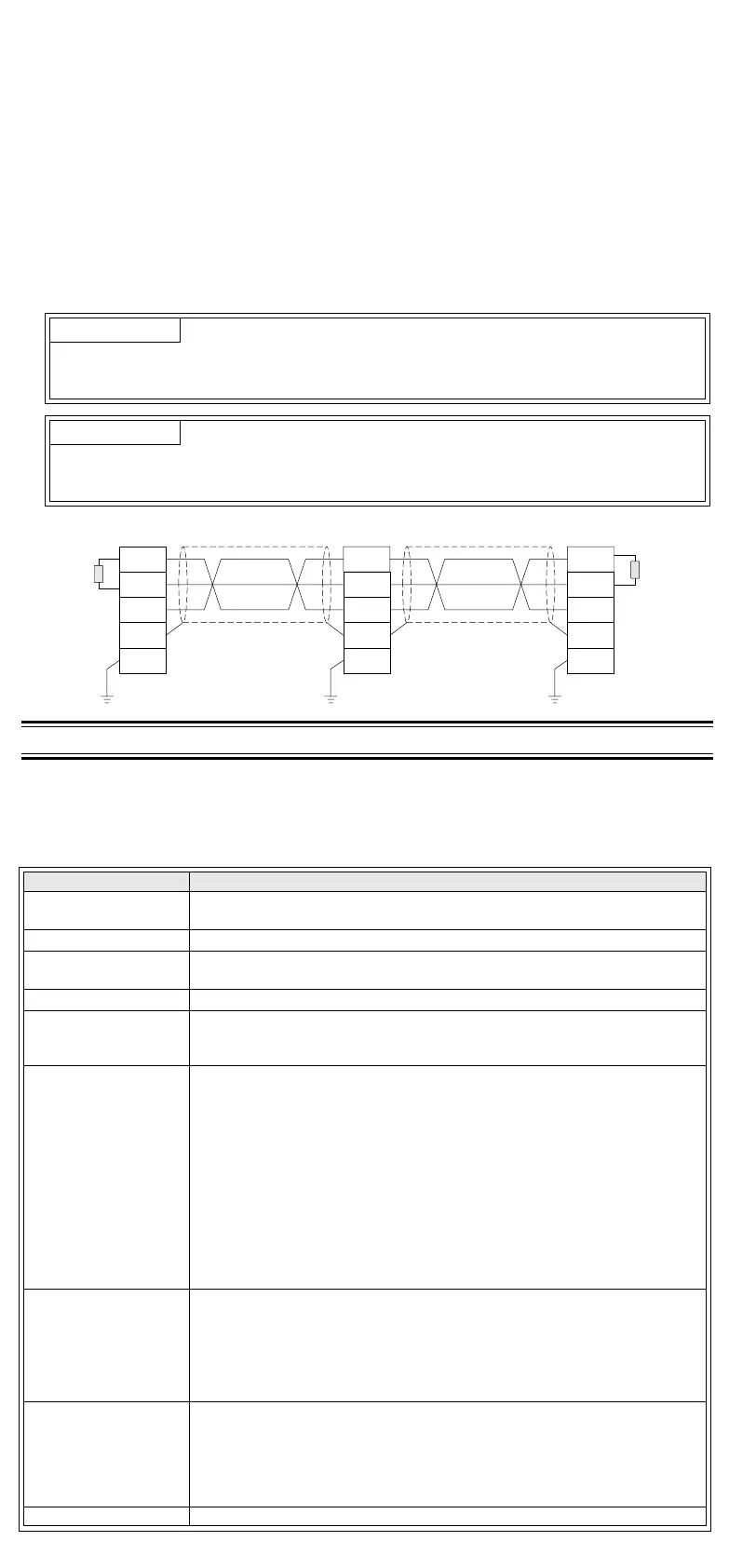
2.3 Module Wiring with Dedicated CC-Link Cables
This section describes the connection method of dedicated CC-Link cables.
• The cables can be connected without regard to the station number.
• Make sure to connect a terminal resistor (offered as an accessory of the module) between the
terminals DA and DB in modules at both ends.
• In the CC-Link system, the terminal resistor to be connected varies depending on the used cable.
- When a dedicated CC-Link cable is used: 110
Ω
, 1/2 W (brown, brown and brown)
- When a dedicated high-performance CC-Link cable is used: 130
Ω
, 1/2 W (brown, orange and
brown)
• The master module can be connected besides to the both ends.
• Star connection is not allowed.
• The figure below shows the connection method.
3. SPECIFICATION
3.1 General Specification
Dielectric strength: 500V AC for 1 minute (between the case and the PLC ground)
Other specification is equivalent to that of the PLC main unit.
3.2 Performance Specification
Important
Make sure to use only one type of cable (dedicated CC-Link cables OR dedicated CC-Link high-
performance cables).
If both types of cables are used together, normal data transmission cannot be guaranteed.
Point
The shielded dedicated CC-Link cable should go through the terminals SLD and FG in each
module, and both ends should be grounded (Class D = solid grounding).
The terminals SLD and FG are connected each other inside the module.
Item Specification
Applicable function
Master station function (The local station and standby master station functions
are not provided.)
CC-Link version Ver.1.10
Transmission speed
Selectable (by rotary switch) among 156 kbps, 625 kbps, 2.5 Mbps, 5 Mbps
and 10 Mbps
Station number 0 (set by rotary switch)
Maximum total cable
length (maximum
transmission distance)
1,200 m maximum
Varies depending on the transmission speed. (Refer to USER’S MANUAL.)
Maximum number of
connected modules
• Remote I/O stations: 7 maximum (Each station occupies 32 I/O points of
the PLC.)
• Remote device stations: 8 maximum (The following condition must be
satisfied.)
{(1
×
a)+(2
×
b)+(3
×
c)+(4
×
d)}
≤
8
a: Number of remote device stations occupying 1 station
b: Number of remote device stations occupying 2 stations
c: Number of remote device stations occupying 3 stations
d: Number of remote device stations occupying 4 stations
• Number of remote I/O stations + Number of remote device stations
≤
15
"Maximum number of I/O points per system" below shall be satisfied.
• For the system configuration calculation, refer to USER’S MANUAL.
Maximum number of I/O
points per system
• Connection is allowed as far as the following condition is satisfied:
(Actual number of I/O points of PLC) + (Number of points occupied by
special extension blocks) + (Number of points occupied by FX
2N
-16CCL-
M: 8) + (32
×
Number of remote I/O modules)
≤
256 (FX
2N
/FX
2NC
Series
PLC) or 128 (FX
1N
Series PLC)
• For the system configuration calculation, refer to USER’S MANUAL.
Number of link points
per station
Remote I/O station : Remote I/O = 32/32 (RX/RY) points
Remote device station : Remote I/O = 32/32 (RX/RY) points
Remote register = 4 (RWw) points
(master station
→
remote device station)
Remote register = 4 (RWr) points
(remote device station
→
master station)
Communication method
Polling method
DA
DB
DG
SLD
FG
DA
DB
DG
SLD
FG
DA
DB
DG
SLD
FG
Dedicated CC-Link cable Dedicated CC-Link cable
Master module Remote module Remote module
Terminal
resistor
Terminal
resistor
*1 Dedicated CC-Link cables and dedicated high-performance CC-Link cables cannot be used at the
same time. Only either type of cables are available.
Attach a terminal resistor in accordance with the cable type.
*2 When an FX
2NC
Series PLC is connected, the interface FX
2NC
-CNV-IF is required.
Synchronous method Frame synchronous method
Encoding method NRZI method
Transmission path type Bus (RS-485)
Transmission format In conformance to HDLC Standard
Error control method
CRC(X
16
+X
12
+X
5
+1)
Connection cable
Dedicated CC-Link cable/Dedicated high-performance CC-Link cable
*1
RAS function
• Automatic return function
• Slave station cutoff function
• Error detection by link special relay/register
Number of times of
parameter registration
to EEPROM
Approximately 10,000 times
Connectable PLC
FX
1N
, FX
2N
(V 2.20 or later) and FX
2NC
(V 2.20 or later)
*2
Series PLC
Number of occupied
I/O points
• 8 I/O points of FX Series PLC (8 points in total. The ratio between inputs
and outputs is arbitrary.)
• When remote I/O station is connected, 32 points per station are occupied.
Communication with PLC
By FROM/TO instructions via the buffer memory
Note
• Scan method: Asynchronous mode
• Automatic refresh: Not provided
• Local station function: Not provided
• Standby master station function: Not provided
• Intelligent device station connection function: Not provided
•FX
2N
-32ASI-M AS-i master block: Cannot be connected concurrently.
Operation indication
POWER : Lit while 24V DC is supplied from outside.
L RUN : Lit while communication is normal.
L ERR : Lit when communication error has occurred.
SD : Lit while data is being transmitted.
RD : Lit while data is being received.
24V DC external power
supply
Supplied from 24V DC (150 mA) external terminal block.
5V DC internal power
supply
5V DC is self-supplied. 5V DC of PLC is not used.
Accessories
Terminal resistor
• For standard cable:
110
Ω
, 1/2 W (color cable: brown, brown and brown), 2 cables
• For high performance cable:
130
Ω
, 1/2 W (color cable: brown, orange and brown), 2 cables
Special block number label
MASS (Weight) 0.4 kg (0.88 lbs)
Item Specification
Manual number : JY992D93201
Manual revision: B
Date : MAR. 2003
JY992D93201B
Effective MAR. 2003
Specifications are subject to
change without notice

 Loading...