H2i-R2-14
PURY-HP-T(S)KMU,-Y(S)KMU (September 2014)
© 2014 Mitsubishi Electric US, Inc.
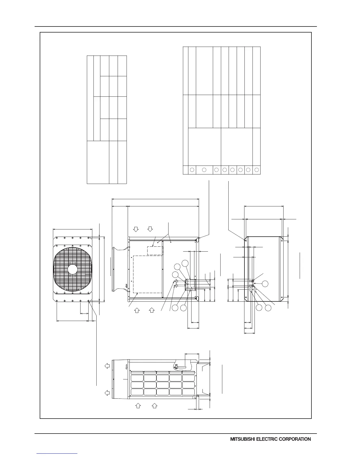
2. EXTERNAL DIMENSIONS
PURY-HP72, 96YKMU-A(-BS)
Unit : mm(in)
(1) (1)
(3/4)
(5/8)
(1-25/32)
(2-9/16)
(1-3/4)
(2-15/32)
(7/8)
(1-3/8)
(1-11/32)
(2-1/16)
(3-23/32)(5-29/32)
(3-1/16)(5-17/32)
(3/4) (1) (1)
(7/8)
Connecting pipe specifications
Note1. Please refer to the next page for information
regarding necessary spacing around the
unit and foundation work.
2. At brazing of pipes, wrap the refrigerant service valve
with wet cloth and keep the temperature of
refrigerant service valve under 120°C(248°F).
Refrigerant service
valve <High pressure>
Refrigerant service
valve <Low pressure>
Refrigerant service valve
<Low pressure>
Refrigerant service valve
<High pressure>
(5-3/4)
(1-3/16)
(1-3/16)
(29-5/32)
(Mounting pitch)
(26-23/32~26-15/16)
(26-13/16)
(Mounting pitch)
(3-5/32) (3-5/32)
(10-11/32)
(3-5/16)
(3-23/32)
(10-23/32) 272
(11-7/8) 301
(8-15/16) 227
(2-1/4)(2-1/4)
(13/16)
(13/16)
(3-17/32)
(3-1/16)
1
(9-29/32) 251
(9-5/16) 236
(10-23/32) 272
(11-15/16)
(25/32)(25/32)
(2-25/32)
=(5-29/32)X4
(23-5/8)
<Snow hood attachment hole>
4X5-ø4.6 (3/16) Hole
(Make hole at the plastic fan guard
for snow hood attachment)
Intake
air
Discharge air
Control box
Intake
air
Service
panel
Intake
air
<Sling hole>
3
6
2
4
5
8
2X2-14(9/16)X20(13/16) Oval hole
2X2-80(3-5/32)X35(1-13/32) Oval hole
7
*1 Use the pipe joint(field supply) and connect to the refrigerant service
valve piping.
High
pressure
ø25.4
Low
pressure
Service valveRefrigerant pipe
Diameter
*1
High
pressure
Low
pressure
Model
PURY-HP72YKMU-A(-BS)
ø25.4
ø19.05 Brazed
ø15.88 Brazed
*1
ø45 Knockout hole
Specifications
ø43.7 or ø22.2 Knockout hole
ø62.7 or ø34.5 Knockout hole
Front through hole
Bottom through hole
Bottom through hole
Front through hole
Front through hole
For wires
Usage
Front through hole
Front through hole
(Uses when twinning
kit (optional
parts) is mounted.)
140 × 77 Knockout hole
150 × 94 Knockout hole
Bottom through hole
For pipes
ø52 Knockout hole
For transmission cables
ø34 Knockout hole
ø65 Knockout hole
PURY-HP96YKMU-A(-BS)
ø19.05 Brazed
*1
ø25.4
*1
ø25.4
ø22.2 Brazed
Transformer box
58 (2-5/16)
75 (2-31/32)
(8-9/16) 217
(5-23/32) 145
146 (5-3/4)
146
83 (3-9/32)
262
(740)
150 (5-29/32)
57
54 (2-5/32)
19.5
80 1060 (41-3/4)
586 (23-3/32)
19.5
57
94 84
121 (4-25/32)
600=150×4
20
1220 (48-1/16)
150 (5-29/32)
1650 (64-31/32)
196 (7-23/32)
1347 (53-1/16)
89
303
20
740 (29-5/32)
70
1181 (46-1/2)
140 (5-17/32)
80
77
681(678~684)29.5 29.5
Bottom view
Left side view
Front view
Top view
NO.
1
2
3
4
6
5
8
7
 Loading...