EasyManua.ls Logo

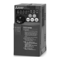
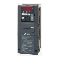
Mitsubishi 700 Series - User Manual

Mitsubishi 700 Series
280 pages
Print Icon
To Next Page IconTo Next Page
Loading...
November 2017
INVERTER
Plug-in option
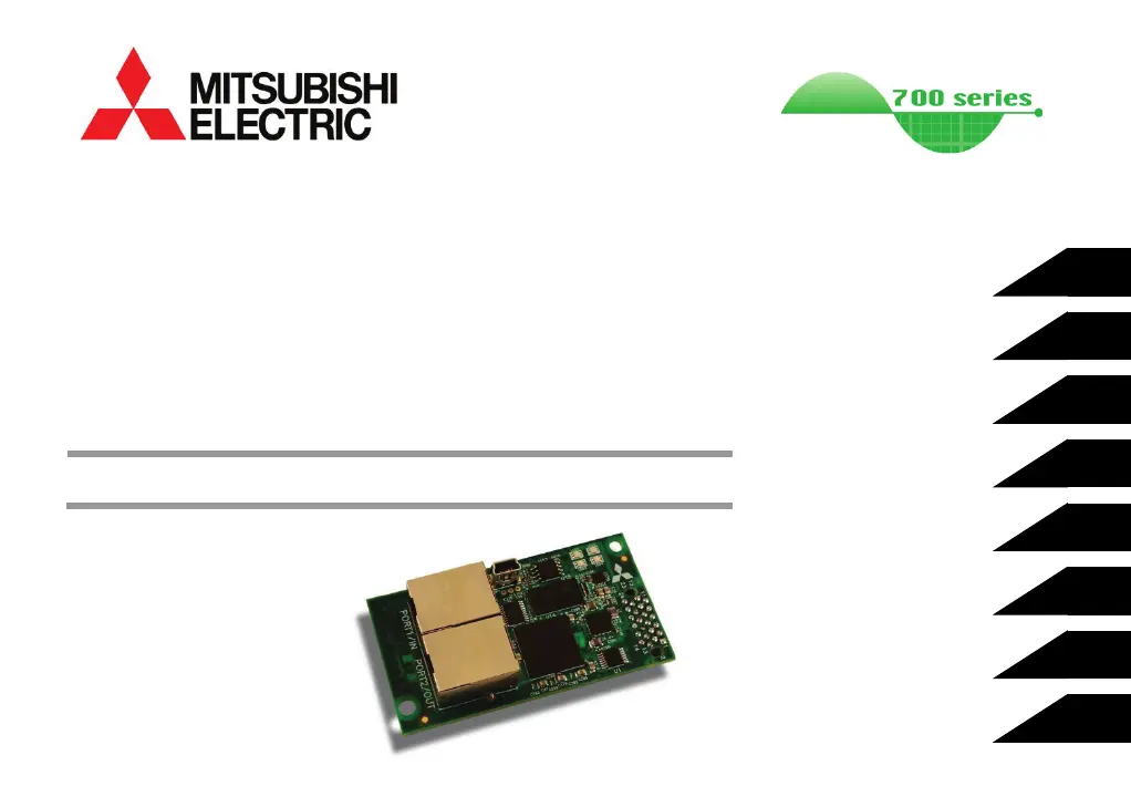
A7NETH-2P
INSTRUCTION MANUAL
Ethernet multiprotocol communication interface
REGISTER NUMBERING
PRE-OPERATION INSTRUCTIONS
INSTALLATION
CONFIGURATION STUDIO
INVERTER SETTINGS
WEB SERVER
FILESYSTEM
FIRMWARE
3
2
1
4
6
7
8
5

Table of Contents

Questions and Answers

  • M
    Monica DavisNov 21, 2025
    How to fix no communication between network and Mitsubishi 700 card?
    • K
      kwellsNov 21, 2025
      If there are no communications between the network and the Mitsubishi Inverter card, first confirm that the card is running normally (Module Status LED is not blinking red) and connected to the local Ethernet network. Ensure that the card is programmed with compatible network settings (consult your network administrator). Confirm that the destination IP address programmed into the controller equipment or computer matches that of the interface card, as displayed by the studio. Also, confirm that intermediate firewalls or routers have been configured to allow access to the interface via the applicable TCP/UDP ports. Try a known working Ethernet cable and switch. If attempting to access the web server on a computer whose web browser is configured to use a proxy server, ensure that the proxy s...
  • M
    michaelcobbAug 25, 2025
    How to unlock operation panel on Mitsubishi 700 Inverter?
    • M
      Mary PopeAug 26, 2025
      To release the operation panel lock on the Mitsubishi Inverter, press the lock button for 2 seconds.
  • L
    Linda JacksonAug 27, 2025
    What to do if Mitsubishi 700 Inverter shows overload trip error?
    • E
      Eric PughAug 27, 2025
      If the temperature of the output transistor element exceeds the protection level when a current not less than the rated inverter current flows (200% or less), the electronic thermal relay activates, stopping the Mitsubishi Inverter output. To resolve this, try increasing the acceleration/deceleration time or adjusting the torque boost setting.
  • K
    Kevin HawkinsAug 27, 2025
    Why is my Mitsubishi Inverter showing an undervoltage error?
    • S
      Steven PenaAug 27, 2025
      If the Mitsubishi Inverter's power supply voltage decreases, the control circuit won't function normally. Check the power supply system equipment, including the power supply itself, to resolve this issue.
  • B
    brooksjoshuaAug 28, 2025
    How to fix a write disable error on a Mitsubishi Inverter?
    • A
      Amber RodriguezAug 28, 2025
      A write disable error on your Mitsubishi Inverter can occur due to several reasons. First, it could be because you're trying to change a parameter when Pr. 77 (Parameter write selection) is set to disable writing. Check the setting of Pr. 77 to resolve this. Second, the frequency jump setting range might be overlapping; review the settings of Pr. 31 to Pr. 36 (frequency jump). Finally, the PU and inverter may not be communicating correctly; check their connection.
  • J
    Julia RoseSep 16, 2025
    What causes Studio to fail accessing the file system of Mitsubishi 700?
    • S
      Sharon KelleySep 16, 2025
      If Studio cannot access the file system of your Mitsubishi Inverter, the card’s file system may be corrupt. Format the card’s file system and then restore the configuration. If the card cannot be formatted, please contact technical support for instructions to manually format the card’s file system.
  • M
    Mr. David Martinez DVMSep 14, 2025
    Why I am unable to control the Mitsubishi 700 Inverter via network communications?
    • B
      Bailey LittleSep 14, 2025
      If you're unable to control the Mitsubishi Inverter via network communications, ensure the inverter is set to NET mode. The inverter will reject command and parameter write requests from the network if it is not in NET mode. If you are using the inverter’s terminal contacts, refer to the inverter’s instruction manual to determine the appropriate behavior and priority. Also, try clearing all parameter settings to default and reconfiguring the parameters.
  • W
    walkerdawnSep 15, 2025
    What to do if Studio cannot discover the Mitsubishi Inverter card?
    • J
      Jessica BerrySep 15, 2025
      If Studio cannot discover the Mitsubishi Inverter card, first confirm that the card is running normally and connected via USB or to the local Ethernet network (connecting via USB is preferable). Check that the module and network status LEDs blink the green/red startup sequence when power is initially applied. Also, add the Studio as an exception to your computer’s firewall, add UDP port 4334 as an exception to the firewall, or temporarily disable the computer’s firewall.
  • J
    Jason BrooksSep 6, 2025
    How to resolve a mode designation error on a Mitsubishi Inverter?
    • T
      Tara WilliamsSep 6, 2025
      A mode designation error occurs if a parameter setting is attempted in the External or NET operation mode with Pr. 77 not set to "2" on your Mitsubishi Inverter. First, ensure the operation mode is set to PU operation mode. Then, set the operation mode to "PU operation mode" before making parameter settings.
  • R
    Ricky MaysSep 4, 2025
    How to troubleshoot output phase loss on a Mitsubishi Inverter?
    • A
      Alison BellSep 4, 2025
      Output phase loss on a Mitsubishi Inverter occurs if one of the three phases (U, V, W) on the inverter's output side is lost during operation. Ensure the cables are properly wired.

Summary

PRE-OPERATION INSTRUCTIONS

Product Overview

Introduces the A7NETH-2P Ethernet communication interface and its capabilities.

Features and Specifications

Details the interface's features and hardware specifications.

Inverter Compatibility

Lists compatible inverter models and series for the plug-in option.

Unpacking and Product Confirmation

Instructions for checking received items and confirming product integrity.

LED Indicators

Explains the function of the LEDs on the interface for status indication.

INSTALLATION

Pre-Installation Instructions

Essential safety precautions before proceeding with installation.

A700 & F700 Installation Procedure

Step-by-step guide for installing the option on A700 and F700 inverters.

E700 Installation Procedure

Step-by-step guide for installing the option on E700 inverters.

Wiring

Instructions and precautions for connecting network cables to the interface card.

INVERTER SETTINGS

Network Setting

Configuration of IP address, subnet mask, and gateway for network connectivity.

Operation Mode Setting

Configuration of how the inverter is controlled (PU, External, Network).

Operation & Speed Command Source

Defines where operation and speed commands originate (RS-485 or option card).

Communication EEPROM Write Selection

Configures where parameter changes are saved (EEPROM or RAM).

REGISTER NUMBERING AND BEHAVIOR

Register Numbers

Explains how inverter parameters are referenced by register numbers.

Inverter Command Register

Details the command register (Register 1) for controlling the inverter.

Frequency Command Register

Explains the frequency command registers (Register 2 and 3) for speed control.

Inverter Status Register

Describes the register (Register 100) for monitoring inverter status.

MITSUBISHI CONFIGURATION STUDIO

Overview

Introduces the Mitsubishi Configuration Studio software for device management.

General Object Editing Activities

Covers common tasks like adding, viewing, updating, and deleting objects.

Ethernet Settings

Configures network-related settings for communication.

Internal Logic Settings

Configures fail-safe behavior and timeout parameters.

Discovery over Ethernet

Explains how the studio finds devices on the network.

EMBEDDED WEB SERVER

Overview

Introduces the web server for remote monitoring and control via web browsers.

Monitor Tab

Provides access to real-time data and status information.

Dashboard Tab

Offers a graphical overview of application variables using gauges and meters.

Customizing the Embedded Web Server

Covers loading custom web content and understanding XTPro protocol.

FILESYSTEM

Overview

Explains the use of the interface card's onboard filesystem for configuration and web server content.

USB with Windows Explorer

Describes accessing the filesystem via USB as a removable disk.

FTP With Windows Explorer

Details accessing the filesystem using FTP with Windows Explorer.

FIRMWARE

Overview

Discusses the ability to update the interface card's embedded firmware.

Update Procedure

Step-by-step instructions for updating the firmware, including safety warnings.

PROTOCOL-SPECIFIC INFORMATION

Modbus;TCP Server

Details Modbus/TCP server support, functions, and register mapping.

EtherNet;IP Server

Covers EtherNet/IP server protocol, including messaging types and examples.

ControlLogix Examples: Setup

Demonstrates setting up a ControlLogix PLC with the communication interface.

ControlLogix Example: EDS Add-On Profile (AOP)

Guides on using EDS Add-On Profiles for EtherNet/IP I/O connections.

ControlLogix Example: I;O Messaging

Demonstrates setting up EtherNet/IP I/O connections with vendor-specific instances.

Allen Bradley CSP (PCCC) Server

Details CSP (PCCC) server support for Allen-Bradley PLCs.

BACnet;IP Server

Covers BACnet/IP server support and its implementation conformance.

PROFINET IO

Covers PROFINET IO protocol, device settings, and configuration examples.

TIA Portal (STEP 7) Hardware Configuration Example

Provides a step-by-step guide for configuring PROFINET using TIA Portal.

TROUBLESHOOTING

Common Problems and Solutions

Provides solutions for common issues like alarms, unresponsiveness, and communication failures.

Mitsubishi 700 Series Specifications

General IconGeneral
Control MethodVector Control
Overload Capacity150% of rated current for 60 seconds
Protection FunctionsOvercurrent, Overvoltage, Undervoltage, Overheat, Short circuit
Communication OptionsRS-485, Profibus, Ethernet
Output Power Range0.4 kW to 630 kW
Cooling MethodForced air cooling (fan) (Varies by model)
Operating Temperature-10 to +50°C (Varies by model, may be derated at higher temperatures)
Storage Temperature-20 to +65°C
Humidity95% RH or less (non-condensing)
AltitudeUp to 1000 m above sea level (Derating may be required above 1000 m)
Enclosure RatingIP20
ModelFR-A700, FR-F700, FR-E700, FR-D700, FR-S700

Related product manuals