EasyManuals Logo

Mitsubishi 700 Series User Manual

Mitsubishi 700 Series
280 pages
To Next Page IconTo Next Page
To Previous Page IconTo Previous Page
Page #257 background imageLoading...
Page #257 background image
PROTOCOL-SPECIFIC INFORMATION
244
9.9.7.3 Select the IO Controller
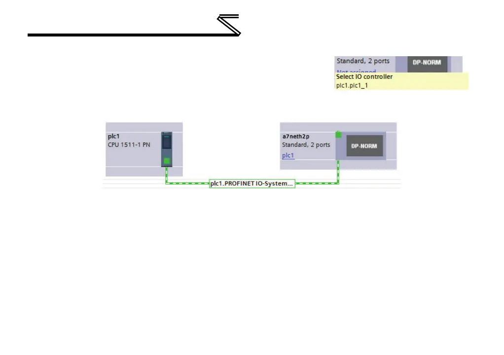
On the device, click “Not assigned” and select the appropriate PLC
PROFINET interface as shown in Figure 82. This will assign the
device to the PROFINET IO system as shown in Figure 83.
Figure 83: PROFINET IO System
9.9.7.4 Assign the I/O Module
Click on the device and then click on the Device view tab. In the Hardware catalog, expand Module
and add a module “IN: XX WORDS, OUT: YY WORDS” into Slot 1. The module will determine the input
and output sizes. In this example, the module “IN: 02 WORDS, OUT: 02 WORDS” is selected. Select a
module with the appropriate input and output sizes for your specific application. Refer to Figure 84.
Figure 82: Select IO Controller

Table of Contents

Questions and Answers:

Question and Answer IconNeed help?

Do you have a question about the Mitsubishi 700 Series and is the answer not in the manual?

Mitsubishi 700 Series Specifications

General IconGeneral
Control MethodVector Control
Overload Capacity150% of rated current for 60 seconds
Protection FunctionsOvercurrent, Overvoltage, Undervoltage, Overheat, Short circuit
Communication OptionsRS-485, Profibus, Ethernet
Output Power Range0.4 kW to 630 kW
Cooling MethodForced air cooling (fan) (Varies by model)
Operating Temperature-10 to +50°C (Varies by model, may be derated at higher temperatures)
Storage Temperature-20 to +65°C
Humidity95% RH or less (non-condensing)
AltitudeUp to 1000 m above sea level (Derating may be required above 1000 m)
Enclosure RatingIP20
ModelFR-A700, FR-F700, FR-E700, FR-D700, FR-S700

Related product manuals