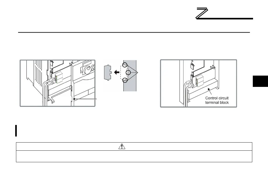
2.4 Wiring
When installing the option card into an FR-A720-00900-NA (FR-A740-00440-NA) or smaller inverter,
remove the wiring access knockout on the front cover and route the network cable through the opening.
When installing the option card into an FR-A720-01150-NA (FR-A740-00570-NA) or larger inverter,
route the network cable through the space adjacent to the control circuit terminal block.
FR-A720-00900-NA (FR-A740-00440-NA)
and smaller
FR-A720-01150-NA (FR-A740-00570-NA)
Remove front cover wiring
access knockout and trim any
excess flashing that may
cause cable damage
If the front cover wiring access knockout is removed, the protective structure (JEM1030)
changes to open type (IP00).
Use caution during wiring to prevent any cable fragments and wire strands from falling into the inverter.
Equipment damage may result if power is applied to the inverter in the presence of conductive debris.
excess
flashing

 Loading...


