2.2.2 Installation of the Communication Option on Control Board
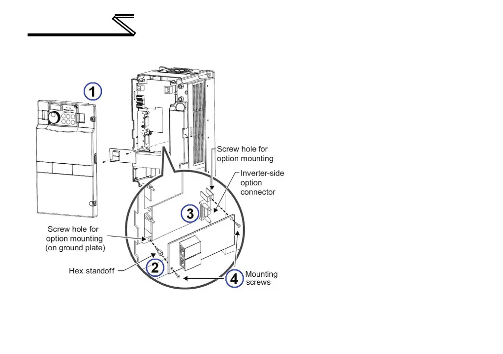
1) Remove the inverter’s front cover.
2) Locate option connector 3 (lowermost
connector) and screw the included
M3x10mm hex standoff into the
corresponding ground plate screw hole
(rated torque 0.56Nm to 0.75Nm).
3) Securely attach the option card to the
inverter’s option connector. Ensure that
the option card is fully seated on the
inverter’s option connector and the hex
standoff.
4) Secure the upper-right corner of the
option card with the included M3x6mm
pan head mounting screw. Secure the
lower-left corner of the option card with
the included M3x6mm flat head
mounting screw. If the screw holes do
not line up, the option card connector
may not be fully seated on the inverter’s
option connector and the hex standoff.

 Loading...


