PROTOCOL-SPECIFIC INFORMATION
9.2.12 ControlLogix Example: I/O Messaging
This section will demonstrate how to setup and use an EtherNet/IP I/O connection via vendor-specific
assembly instances 100 & 150 or 20 & 70 or 20 & 71. EtherNet/IP I/O messaging allows the inverter’s
registers to be directly mapped into tags in the ControlLogix PLC. Once an I/O connection is
established, it is automatically synchronized at an interval defined by the Requested Packet Interval
(RPI).
16) Switch to offline mode.
17) Right click on the 1756-ENBT node
under the I/O Configuration in the
controller organizer view and
choose “New Module…”
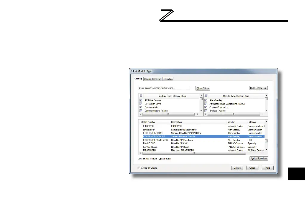
18) Choose “Generic Ethernet Module”
in the Select Module dialog box and
click “Create”. Refer to Figure 40.
19) The module properties dialog box
will open (refer to Figure 41). Enter
a Name which will allow easy
identification of the inverter on the
network (the tags created in
RSLogix 5000 will be derived from
this Name). Because all inverter
data is stored as 16-bit registers,
Figure 40: Adding a New Generic Ethernet Module

 Loading...


