-
34
-
PHA001Z173
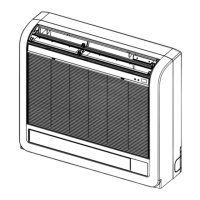
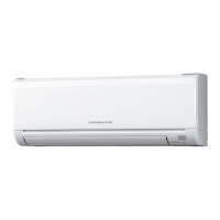
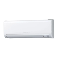
(3) Wall mounted type (FDK)
Models FDK15KXZE1-W, 22KXZE1-W, 28KXZE1-W, 36KXZE1-W, 45KXZE1-W
Model
FDK15KXZE1-W FDK22KXZE1-W FDK28KXZE1-W FDK36KXZE1-W FDK45KXZE1-W
Nominal cooling capacity*1
kW
1.5 2.2 2.8 3.6 4.5
Nominal heating capacity*2 1.7 2.5 3.2 4.0 5.0
Power source
1 Phase 220-240V 50Hz / 220V 60Hz 1 Phase 220-240V 50Hz / 220V 60Hz 1 Phase 220-240V 50Hz / 220V 60Hz 1 Phase 220-240V 50Hz / 220V 60Hz 1 Phase 220-240V 50Hz / 220V 60Hz
Power consumption
Cooling
kW
0.020 - 0.020 / 0.020 0.020 - 0.020 / 0.020 0.020 - 0.020 / 0.020 0.030 - 0.030 / 0.030 0.030 - 0.030 / 0.030
Heating
0.020 - 0.020 / 0.020 0.020 - 0.020 / 0.020 0.020 - 0.020 / 0.020 0.030 - 0.030 / 0.030 0.030 - 0.030 / 0.030
Running current
Cooling
A
0.18 - 0.16 / 0.18 0.18 - 0.16 / 0.18 0.18 - 0.16 / 0.18 0.27 - 0.25 / 0.27 0.27 - 0.25 / 0.27
Heating
0.18 - 0.16 / 0.18 0.18 - 0.16 / 0.18 0.18 - 0.16 / 0.18 0.27 - 0.25 / 0.27 0.27 - 0.25 / 0.27
Sound Power Level
Cooling
dB(A)
54 55 55 58 58
Heating
54 55 55 58 58
Sound Pressure Level
Cooling
P-Hi : 38 Hi : 34 Me : 31 Lo : 28 P-Hi : 38 Hi : 36 Me : 30 Lo : 27 P-Hi : 38 Hi : 36 Me : 30 Lo : 27 P-Hi : 40 Hi : 38 Me : 33 Lo : 28 P-Hi : 43 Hi : 41 Me : 36 Lo : 33
Heating
P-Hi : 38 Hi : 34 Me : 31 Lo : 28 P-Hi : 38 Hi : 36 Me : 30 Lo : 27 P-Hi : 38 Hi : 36 Me : 30 Lo : 27 P-Hi : 40 Hi : 38 Me : 33 Lo : 28 P-Hi : 43 Hi : 41 Me : 36 Lo : 33
Exterior dimensions
Height x Width x Depth
mm 290 × 870 × 230 290 × 870 × 230 290 × 870 × 230 290 × 870 × 230 290 × 870 × 230
Exterior appearance
(Munsell color)
Fine Snow
(8.0Y9.3 / 0.1) near equivalent
Fine Snow
(8.0Y9.3 / 0.1) near equivalent
Fine Snow
(8.0Y9.3 / 0.1) near equivalent
Fine Snow
(8.0Y9.3 / 0.1) near equivalent
Fine Snow
(8.0Y9.3 / 0.1) near equivalent
Net weight*3 kg 11.5 11 11 11.5 11.5
Refrigerant equipment Heat exchanger
Louver n & inner grooved tubing Louver n & inner grooved tubing Louver n & inner grooved tubing Louver n & inner grooved tubing Louver n & inner grooved tubing
Refrigerant control Electronic Expansion Valve Electronic Expansion Valve Electronic Expansion Valve Electronic Expansion Valve Electronic Expansion Valve
Air handling equipment Fan type & Q'ty
Tangential fan × 1 Tangential fan × 1 Tangential fan × 1 Tangential fan ×1 Tangential fan ×1
Fan motor
W 42 42 42 42 42
Starting method Direct line start Direct line start Direct line start Direct line start Direct line start
Air ow
Cooling
m
3
/min
P-Hi : 5.7 Hi : 5 Me : 4.5 Lo : 3.6 P-Hi : 8.5 Hi : 8 Me : 6 Lo : 5 P-Hi : 8.5 Hi : 8 Me : 6 Lo : 5 P-Hi : 11 Hi : 10 Me : 8 Lo : 7 P-Hi : 12 Hi : 11 Me : 9 Lo : 8
Heating
P-Hi : 5.7 Hi : 5 Me : 4.5 Lo : 3.6 P-Hi : 8.5 Hi : 8 Me : 6 Lo : 5 P-Hi : 8.5 Hi : 8 Me : 6 Lo : 5 P-Hi : 11 Hi : 10 Me : 8 Lo : 7 P-Hi : 12 Hi : 11 Me : 9 Lo : 8
Available static pressure Pa 0 0 0 0 0
Outdoor air intake Not Possible Not Possible Not Possible Not Possible Not Possible
Air lter, Q'ty Polypropylene net × 2 (Washable) Polypropylene net × 2 (Washable) Polypropylene net × 2 (Washable) Polypropylene net × 2 (Washable) Polypropylene net × 2 (Washable)
Shock & vibration absorber Rubber sleeve (for fan motor) Rubber sleeve (for fan motor) Rubber sleeve (for fan motor) Rubber sleeve (for fan motor) Rubber sleeve (for fan motor)
Insulation (Noise & heat) Polyurethane form Polyurethane form Polyurethane form Polyurethane form Polyurethane form
Operation control
Remote control switch (Option)
Wired : RC-EX3A
Wireless : RCN-K-E2
Wired : RC-EX3A
Wireless : RCN-K-E2
Wired : RC-EX3A
Wireless : RCN-K-E2
Wired : RC-EX3A
Wireless : RCN-K-E2
Wired : RC-EX3A
Wireless : RCN-K-E2
Room temperature control Thermostat by electronics Thermostat by electronics Thermostat by electronics Thermostat by electronics Thermostat by electronics
Safety equipment
Overload protection for fan motor
Frost protection thermostat
Overload protection for fan motor
Frost protection thermostat
Overload protection for fan motor
Frost protection thermostat
Overload protection for fan motor
Frost protection thermostat
Overload protection for fan motor
Frost protection thermostat
Installation data
Refrigerant piping size
Liquid line :
φ
6.35 (1/4")
Gas line :
φ
9.52 (3/8")
Liquid line :
φ
6.35 (1/4")
Gas line :
φ
9.52 (3/8")
Liquid line :
φ
6.35 (1/4")
Gas line :
φ
9.52 (3/8")
Liquid line :
φ
6.35 (1/4")
Gas line :
φ
12.7 (1/2")
Liquid line :
φ
6.35 (1/4")
Gas line :
φ
12.7 (1/2")
Connecting method Flare piping Flare piping Flare piping Flare piping Flare piping
Refrigerant R32 R32 R32 R32 R32
Drain hose
Connectable with VP16 (I.D.16) Connectable with VP16 (I.D.16) Connectable with VP16 (I.D.16) Connectable with VP16 (I.D.16) Connectable with VP16 (I.D.16)
Insulation for piping Necessary (both Liquid & Gas line)
Necessary (both Liquid & Gas line) Necessary (both Liquid & Gas line) Necessary (both Liquid & Gas line) Necessary (both Liquid & Gas line)
Accessories Mounting kit, Drain hose Mounting kit, Drain hose Mounting kit, Drain hose Mounting kit, Drain hose Mounting kit, Drain hose
Exterior dimensions PHA001Z176 PHA001Z176 PHA001Z176 PHA001Z176 PHA001Z176
Electrical wiring PHA001Z178 PHA001Z178 PHA001Z178 PHA001Z178 PHA001Z178
Adapted to RoHS directive
OPTION Model Specificatio
Remote
control
Wired RC-EX3A PJZ000Z333
Wired RC-E5 PJZ000Z295
Wired RCH-E3 PJZ000Z272
Wireless FDK15-56 RCN-K-E2 PHA001Z123
Wireless FDK71-90 RCN-K71-E2 PHA001Z124
Motion sensor LB-KIT2 PJZ000Z341
Notes
(1)
The data are measured at the following conditions.
Item Indoor air temperature Outdoor air temperature
Standards
Operation DB WB DB WB
Cooling*1 27
℃
19
℃
35
℃
24
℃
ISO5151-T1
Heating*2 20
℃
7
℃
6
℃
(2) This packaged air-conditioner is manufactured and tested in conformity with the standard.
ISO-T1 "UNITARY AIR-CONDITIONERS"
(3) Sound level indicates the value in an anechoic chamber.
During operation these value are somewhat higher due to ambient conditions.
(4) Select the breaker size according to the own national standard.
 Loading...
