73
MECHANICAL STRUCTURE
1 Apply the lithium grease to the bush of the front and rear brackets for assembly.
2 Screw and crimp the nut in the condition which the front bracket is set with slight backlash, none
excessive.
3 Apply the adhesives equivalent to Threebond #1782 to the breather pipe and press it.
4 Assembly of Pinion Shaft
1. Adjust the preload for pinion shaft within 0.39 to
1P^WRNJIFPWROEIIW`DWRLO
seal assembling) by tightening the nut.
Crimp the nut after adjustment.
2. Measure the distance H
and determine the thickness
of liners as follows.
Liner thickness = H-16mm {0.63in}
3. Placing direction of the oil seal for pinion shaft
shall be as shown in the figure. (Spring stays
inside.)
(Unit: mm {in})
5 Assembly of Differential Case Assembly
1. Make sure the backlash for the pinion gear and side
gear is within 0.10 to 0.30mm {0.004 to 0.012in}.
2. Apply the adhesives equivalent to Threebond #1374
thto
to
e locking bolt for the ring gear and tighten with
WRUTXHDWWR1P^WR NJIFP
OEIIW`
3. Place the spring pin with the slit toward as shown in
the figure. (Vertical to the shaft)
4.
Apply the lubricant (MOS
2
) to the gears and assemble
it.
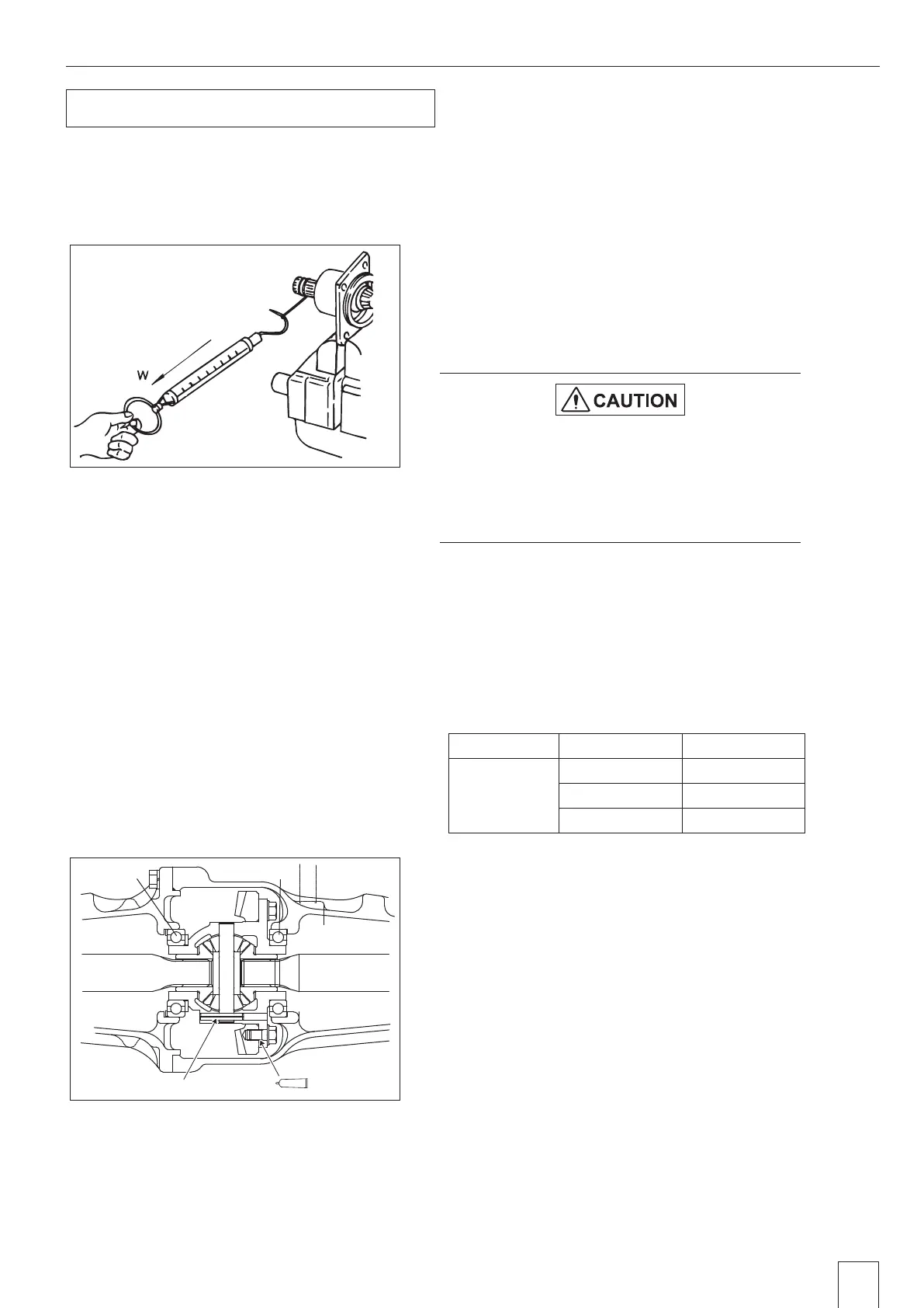
As an easier method for measuring the preload,
after temporarily tightening the nut, wind the shaft
of pinion shaft with rope and pull with spring
balance. (F = 39.2 to 58.8N {4.0 to 6.0kgf, 8.8 to
13.2lbf})
Item Thickness Usable Limit
Liner "J"
0.10 {0.004} 1023 2136 001
0.20 {0.008} 1023 2137 001
0.40 {0.016} 1023 2138 001
GS7W3-167
Spring pin
Bond
GZ3W26-021
6010
6010
1. Assembly of Front Axle
 Loading...