61
OPERATING PROCEDURE PHOTOS
1. Removing the electrical parts
(
1
)
Remove the 5 screws and the top panel.
(
3 screws in
front and 2 screws in rear
)
(
2
)
Remove the screw of the cover panel. To remove the
cover panel, pull it toward you and unhook the catch-
es from the side panel.
(
3
)
Remove the screw of the service panel. To remove the
service panel, pull it down toward you and unhook the
catches on the both sides.
2. Removing the fan motor
(
1
)
Remove the 3 screws of the front panel. Open the
front panel to a 45-degree angle. Then lift it and
unhook the 3 catches to remove.
(
2
)
Remove the propeller nut and the propeller.
(
3
)
Remove the 3 screws and the fan motor.
Disconnect the lead connectors.
Photo 1
Photo 2
Photo 3
Top panel
Service panel
Panel cover
Front panel
Deicer P.C. board
Transformer
Fan motor
capacitor
Contactor
Terminal blockScrews
Screws
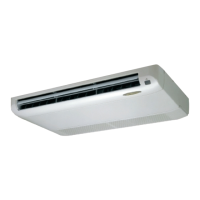
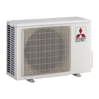
12-4. MUCFH-24NV -
OUTDOOR UNIT
E3
Propeller nut
Valve bed
Lead
connectors
Separator support plate
Motor support
Propeller
fan
OB267--3.qxp 01.4.13 0:55 PM Page 61
 Loading...