6-103 Safety
6Safety
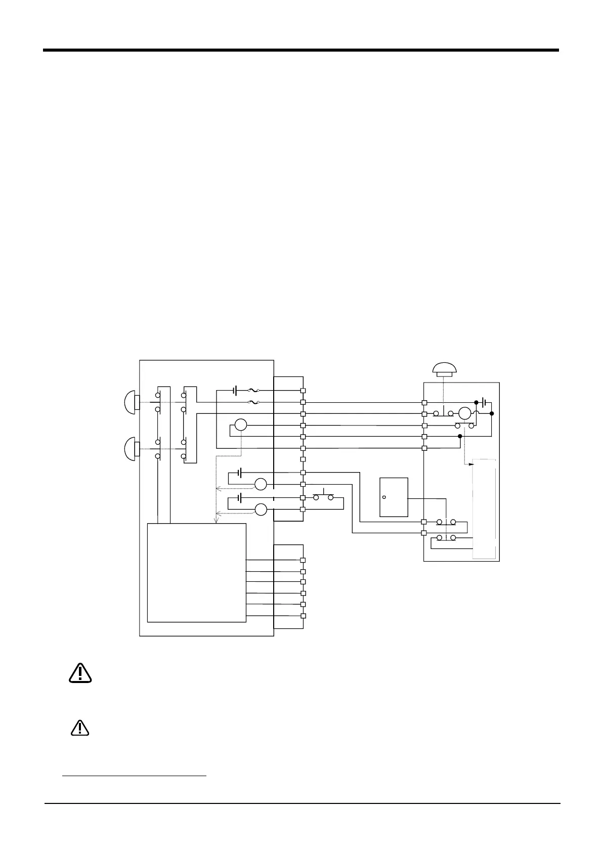
(1) External emergency stop connection [supplementary explanation]
(1) Use a 2-contact type switch for all switches.
(2) Install a limit switch on the safety fence's door. With a constantly open contact (a contact), wire to the door
switch input terminal so that the switch turns ON (is conducted) when the door is closed, and turns OFF (is
opened) when the door is open.
(3) Use a manual-return type 2b-contact for the emergency stop button.
(4) Classify the faults into minor faults (faults that are easily restored and that do not have a great effect) and
major faults (faults that cause the entire system to stop immediately, and that require care in restoration),
and wire accordingly.
[Caution] The emergency stop input (terminal block) on the user wiring in the controller can be used for safety
measures as shown in Fig. 6-1 to Fig. 6-4. Note that there are limits to the No. of switch contacts,
capacity and cable length, so refer to the following and install.
・ Switch contact.............................. Prepare a 2-contact type.
*1)
・ Switch contact capacity........... Use a contact that operates with a switch contact capacity of
approx. 1mA to 100mA/24V.
*1)
If you connect the relay etc., rated current of the coil should use
the relay which is 100mA/24V or less. (Refer to Fig. 6-5)
・ Cable length................................... The length of the wire between the switch and terminal block must
be max. 15m or less. Please use the shield line, in case of the cable
may receive the noise etc. by other equipment, such as servo ampli
-
fier. And, since the ferrite core is attached as noise measures parts,
please utilize.
Fig.6-5 : Limitations when connecting the relay etc.
You should always connect doubly connection of the emergency stop, the door switch,
and the enabling switch. (Connect with both of side-A and side-B of the controller rear
connector) In connection of only one side, if the relay of customer use should break
down, it may not function correctly.
Be sufficiently careful and wiring so that two or more emergency stop switches work
independently. Don't function only on AND conditions (Two or more emergency stop
switch status are all ON).
*1) The minimum load electric current of the switch is more than 5mA/24V.
1A/1B
2A/2B
3A/3B
4A/4B
5A/5B
6A/6B
8A/8B
9A/9B
1A/1B
2A/2B
3A/3B
4A/4B
5A/5B
6A/6B
EMGIN1/2
EMGOUT1/2
Robot controller
Not connected
Error output
Mode output
OP Emergency
stop button
}
RA
RA
RA
7A/7B
}
}
10A/10B
11A/11B
Door switch input
Enabling
device
RA
TB Emergency
stop button
Power supply in the
robot controller
24V
Safety
fence door
Emergency stop switch
(2-contact type)
Peripheral
equipment
Power
supply 24V
Monitor
Circuit
Monitor
Internal emergency
stop circuit
Contactor control
output for additional
axes
CAUTION
CAUTION
 Loading...

