3 Controller
Emergency stop input and output etc. 3-62
3.6 Emergency stop input and output etc.
Do wiring of the external emergency stop, the special stop input, the door switch, and the enabling device from
the "special input/output" terminal connector.
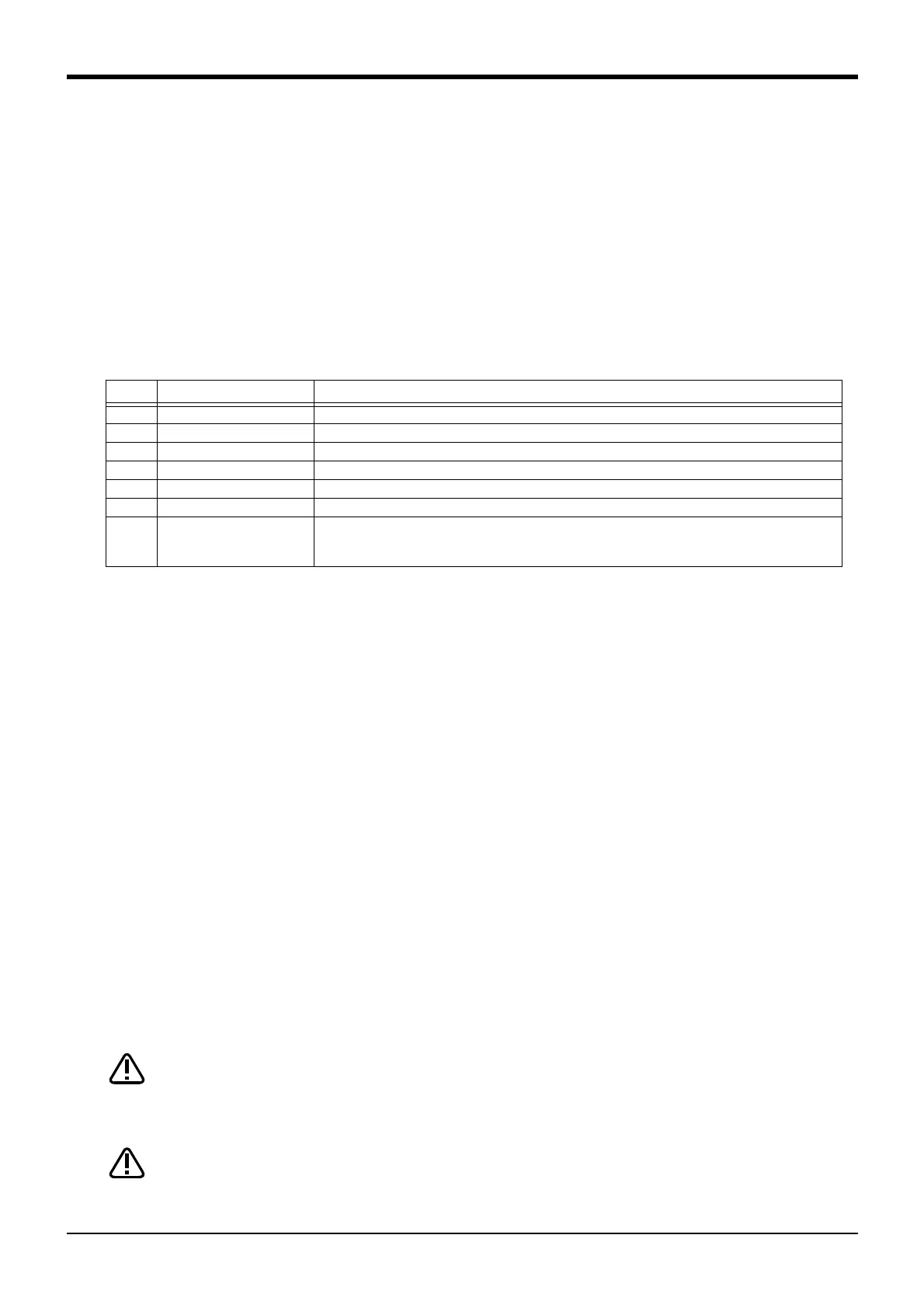
Table 3-5 : Special input/output terminal
*At the time of the power supply OFF, the output point of contact is always open.
[Note] The contact capacity of each input/output terminal is DC24V/10mA - 500mA. Don't connect the
equipment except for this range. The use exceeding contact capacity causes failure.
Pin number assignment of each terminal and the circuit diagram are shown in Fig. 3-20.
3.6.1 Connection of the external emergency stop
The external emergency stop input and door switch input and enabling device input are opened at shipment as
shown in Fig. 3-20.
Connect the external emergency stop switch and door switch with the following procedure.
[Caution] Since the emergency stop, the enabling device, and the door switch circuits are made dual circuits
inside the controller, all the emergency stop switches should use dual contact type. Remove the contact
capacity sticker stuck on the connector (EMGIN, EMGOUT, SKIP) and connect the emergency switch.
1) Prepare the "emergency stop switch", "enabling device" and "door switch".
2) Securely connect the external emergency stop's contacts across 3A-4A, 3B-4B, and the door switch's con
-
tacts across 8A-9A, 8B-9B, and the enabling device switch's contacts across 10A-11A, 10B-11B, on the ter
-
minal block.
[Caution] When wiring the emergency stop switch (double emergency line type) and SKIP input signal, wire both
contacts to the two terminal blocks on the controller. If both contacts are wired to only one of the ter
-
minal blocks, errors cannot be cancelled using the door switch. The cable uses the shielded cable and
installs the ferrite core. Install the ferrite core in less than 30cm from the contact button.
You should always connect doubly connection of the emergency stop, the door switch,
and the enabling switch. (Connect with both of side-A and side-B of the controller rear
connector) In connection of only one side, if the relay of customer use should break
down, it may not function correctly.
Please be sure to check that each function operates normally for the prevention of
malfunction. Surely check that the operation of the emergency stop of the robot
controller, the emergency stop of the teaching pendant, the customer's emergency
stop, etc are normally.
Note1) The level indicates the signal level.
L: Level signal → The designated function is validated when the signal is ON, and is invalidated when the sig
-
nal is OFF.
E: Edge signal → The designated function is validated when the signal changes from the OFF to ON state, and
the function maintains the original state even when the signal then turns OFF.
Note2) Four elements are set in the order of input signal start No., end No., output signal start No. and end No.
Note3) Up to eight points can be set successively in order of start output signal No. and end output signal No.
Item Name Function
Input Emergency stop Applies the emergency stop. Dual emergency line
Input Special stop input Applies the stop. (Refer to Page 66, "3.6.2 Special stop input(SKIP)")
Input Door switch Servo-off. Dual line, normal close (Page 68, "3.6.3 Door switch function")
Input Enabling device Servo-off. Dual line, normal close (Page 68, "3.6.4 Enabling device function")
Output Robot error output Contactor is opening during error occurrence
Output Mode output MANUAL mode: contactor is opening, AUTO mode: contactor is closing.
Output Magnet contactor control
connector output for addi
-
tion axes
When an additional axis is used, the servo ON/OFF status of the additional axis can be synchronized
with the robot arm. (Page 75, "3.8 Magnet contactor control connector output (AXMC) for addition
axes")
CAUTION
CAUTION
 Loading...

