3-75 Magnet contactor control connector output (AXMC) for addition axes
3 Controller
3.8 Magnet contactor control connector output (AXMC) for addition axes
When an additional axis is used, the servo ON/OFF status of the additional axis can be synchronized with the
servo ON/OFF status of the robot itself by using the output contact (AXMC) provided on the rear or inside of the
controller and configuring a circuit so that the power to the servo amplifier for the additional axis can be turned
off when this output is open.
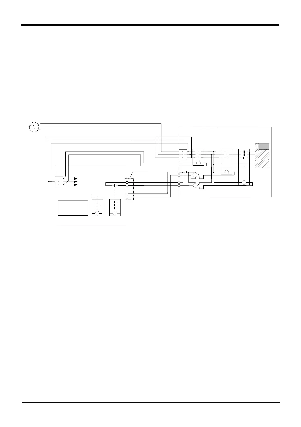
Fig. 3-28 shows an example of its circuit, and Fig. 3-29 show the layout drawings of the output contact
(EMGOUT). When you are using an additional axis, please perform appropriate circuit connections by referring to
these drawings.
Refer to the separate "Additional axis interface Instruction Manual" for details on the additional axis function.
Note1) you use the addition axis function as a user mechanism who became independent of the robot arm, please
do not connect this output signal. Servo-on of the user mechanism may be unable.
Fig.3-28 : Example of circuit for addition axes of Magnet contactor control output
MC2
NV
MC MC1
NV
5B
6B
AXMC2
AXMC1
5A
6A
88
EMGOUT
Amplifier
1) Get the power supply for the controller from the secondary erminal
of short circuit breaker (NV) built in the addition axis amplifier box.
2) Get the power supply for the MC synchronization from the secondary
terminal of short circuit breaker (NV) built in the controller.
To the internal circuit
AXMC is outputted
from the contact
for internal servo
power supplies.
<Robot controller>
<Electric specification>
Note) This output is opened, if the robot turns off the servo
by occurrence of alarm etc.
DC24V 10 to 500mA
Note)
<Addition axis amplifier box>
Note)
 Loading...

