3-43 Names of each part
3
Controller
3.2 Names of each part
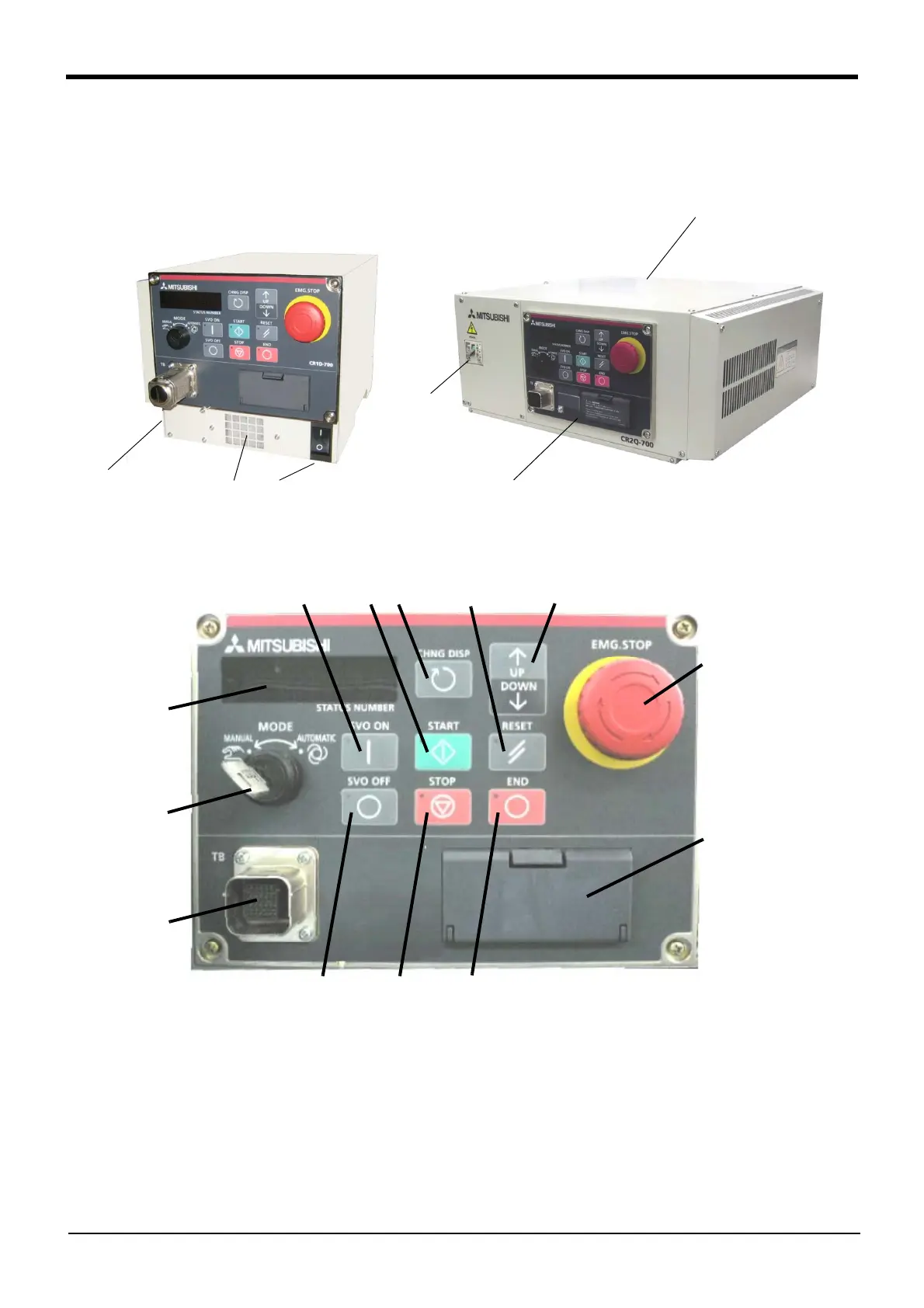
3.2.1 Names of each part of the drive unit
Fig.3-1 : Names of drive unit parts
①
POWER switch..................................This turns the control power ON/OFF. (With earth leakage breaker function)
* 1)
② START button................................... This executes the program and operates the robot. The program is run continuously.
③ STOP button...................................... This stops the robot immediately. The servo does not turn OFF.
④ RESET button.................................... This resets the error. This also resets the program's halted state and resets the program.
⑤ Emergency stop switch ................. This stops the robot in an emergency state. The servo turns OFF.
⑥ CHNGDISP button........................... This changes the details displayed on the display panel in the order of "Override" → "Pro
-
gram No." → "Line No.".
⑦ END button......................................... This stops the program being executed at the last line or END statement.
< DU1A-700 series >
①
②
④
⑤
⑥
⑧
⑬
⑫
⑩
⑨
⑭
⑦
③
⑪
< Operating panel >
⑮
Power cable
clamp
(Side)
< DU2A-700 series >
①
⑮ Power cable
clamp
(Rear)
Operating panel
* The figure is standard specification.
The CE marking specification is the same.
⑯
 Loading...

